I know that this is a very basic question but I really do not know the answer.
I was making simple logic gates using transistors and I used PNP transistor as NOT gate.
I made the following circuit: (A) AND (B) AND (NOT C)
This circuit does not work without the resistors R1,R2 and R3. Why are these resistors important ?
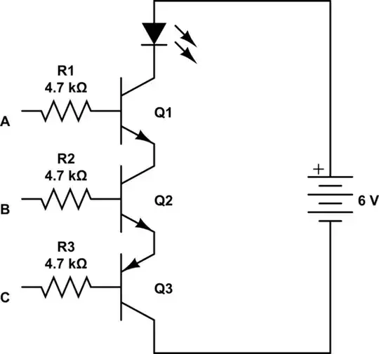
simulate this circuit – Schematic created using CircuitLab
The Following NOT gate does not need a base resistor. I connect Vcc or ground directly to base and it works.
How can it work without resistors although it is very similar to the previous circuit ?

