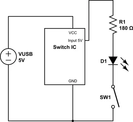
I'm still pretty much a electronics-beginner, I'm currently working on modifying a USB game-pad to use switches instead of buttons and I want LEDs to accompany the switches. The basic solution I was hoping to use looked like the following:
simulate this circuit – Schematic created using CircuitLab
Note that when Input 5V to GND is shorted then IC transmits the button as pressed. The current through the LED is 20mA.
The schematic above makes the LED work but the controller no longer recognizes it as being switched on. So, unable to modify the current going through the switch I instead tried to add a transistor with the resistor and LED separate from the switch, similar to the solution here:
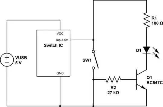
This makes the switch work again but the LED does not power on. It does work when I remove the connection between the switch and GND so I'm assuming all the current goes through the GND-connection and nothing goes to the transistor base. Am I thinking incorrectly or how should I solve this?

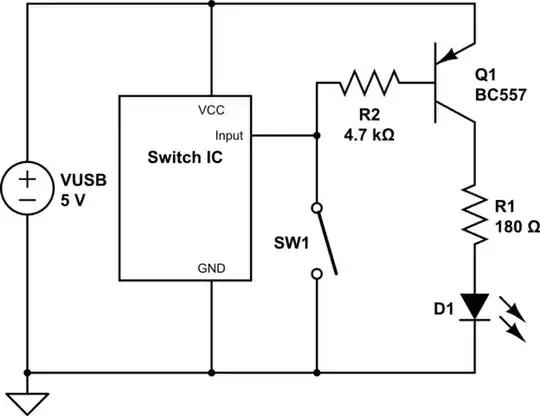
Your solution looks good though, I just need to take some time and go over it and study up a bit. One thought on point nr 1 of PNP downsides, if I add a resistor in line with SW1 wouldn't that just put me in the same situation as I'm in now where the IC wouldn't be satisfied? What is the difference between that and putting a resistor in series when using a NPN BJT?
– SvDvorak Aug 29 '15 at 23:39