I've got a bunch of these integrated H-bridge & driver IC's in my stock and wish to use them in an upcoming design:
http://www.toshiba.com/taec/components2/Datasheet_Sync/201006/DST_TB6593FNG-TDE_EN_27195.pdf
However, these IC's can only drive 3.2A. I would like to augment the current handling capability of these existing IC's to be able to drive about 6A through a solenoid. I do not want to buy new stock of beefier H-bridge/driver IC's, if possible.
The solenoid itself has parameters of R=2ohms, L=1mH
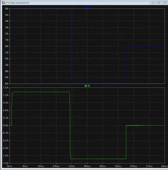
I simulated a proof-of-concept, barebones circuit to augment drive capability consisting of two push-pull pairs that are driven by the H-bridge outputs, and those BJT's then drive the bulk of current through the solenoid. The H-bridge itself is generic; I simply put it together in LTSpice with some high Ron MOSFETs to simulate the current limitation of the IC, for which a macro model does not exist. Results are illustrated below:


Questions about this approach:
(1) Is this a safe way to augment the capability of this IC, or other similar IC's?
(2) What can I add to augmented circuit above to simulate more accurate real-world behavior?
(3) Is this approach ever used in industry? Or is there a better method?
(4) Are there any pitfalls or "gotchas" with the augmented circuit above?
Paralleling these IC's might indeed work; however, paralleling two of these IC's is more expensive than just using a single IC and 4 cheap BJT's
– smoothVTer Jul 14 '15 at 17:03