I'm pretty new to electronics and the first thing I want to have on a PCB is a simple signal source (sinusoidal 12V RMS ; 100 Hz Frequency). To not blow things up I want a current monitoring circuit which should disconnect the source if the load exceeds about 500mA. I came up with the following idea, but since I'm new I'd like to have some review on this:
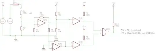 (
(The circuit should output a LOW signal if the current on RL exceeds 500mA and a HIGH signal if the current is not exceeded: $$I_{max} = 500mA$$
The root mean square of the signal is 12V: $$U_{RMS} = 12V$$ The amplitude is approx. 17VDC $$U_{peak} = \sqrt{2} \times U_{RMS} = 16.97V \approx 17V$$
The maximum load is therefore 34Ohms: $$R_{Lmax} = \frac{U_{peak}}{I_{max}} = 34\Omega$$
I'm planning to use a one ohm resistor to monitor the current: $$R_{shunt} = 1\Omega$$ $$P_{shunt} = I^{2} \times R = 0.25W$$
If current is exceeded, the voltage drop across the one ohm resistor should be around 0.5V: $$U_{shunt} = 1\Omega \times I_{max} = 0.5V$$
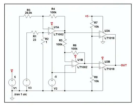
I'm amplifying the voltage with the factor 5 to get exactly 2.5V if the current on the load is 500mA: $$V_{1} = \frac{R3}{R4} + 1 = 5$$ $$U_{OPV1} = U_{shuntmax} \times 5 = 2.5V$$
The comparators have the following supplies:
IC1A & IC1C have +UB=5V and -UB=-5V.
IC1B & IC1D have +UB=5V and -UB=0V.
I know on the schematic all amplifiers have the same IC "name", I didn't bother to change this :(
The comparator IC1C inverts the signal to detect 'reverse' overload current (-500mA results in -2.5V).
Then I'm comparing the 2.5V with both comparators to check if the current is exceeded or not.