0

I'm building LED driver based on current mode control buck converter. My question is quit general. If load is disconnected then output capacitor voltage shoots up. If load is reconnected it gets overcurrent spike from that charged capacitor. If output capacitor cannot be removed, what else can be done? Is there a general approach to this problem?

enter image description here

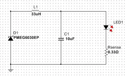
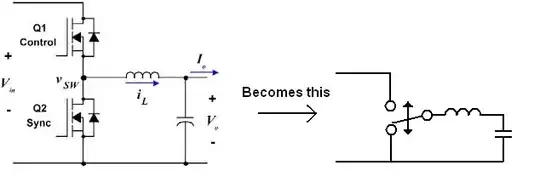
Thats a simplified circuit. If LED is disconnected, output capacitor charges to high voltages and can destruct the LED if it is reconnected.

My biggest worry is if I'm missing something simple and obvious? If not, thats ok, I will do my work somehow.

Vincent
  • 79
  • 6
  • Can you put a constant load resistor on it to help it maintain regulation? Something that draws ~20mA constantly maybe. Are you able to do this for your design? What voltage are you using here? What is the load current for the LED load? Are you doing low or high current? – KyranF Jun 02 '15 at 15:52
  • Show us a schematic as well – KyranF Jun 02 '15 at 15:53
  • Linear technology has several regulator ICs and app notes for hot pluggable support. That should give you a few ideas. – steverino Jun 02 '15 at 15:59
  • KyranF, thank you for your response. I have my design almost complete and tested working, which is quit complex. Thats a buck converter controlled by atmega microcontroller to do variable output currents and PWM. Current range 50ma-2A. But the problem is general I think as I tried to iliustrate with a schematic above. – Vincent Jun 02 '15 at 16:34
  • You can use an auxiliary control loop so that once the voltage rises to the maximum desired level the converter enters voltage regulation mode instead of current regulation mode. – John D Jun 02 '15 at 16:39
  • Is there cabling to the LED? It's not on the same substrate at the driver? Why are you experiencing intermittent load connections? Also, why do you need the output cap? For emissions? Typically, buck current regulators don't require the output capacitance. Can you minimize the value? – M D Jun 02 '15 at 17:09

2 Answers2

0

If instead of using a MOSFET and diode non-synchronous buck regime you chose a synchronous (2 MOSFET) scheme you would get what you want without the hassle of a control loop.

A synchronous buck converter power stage is this: -

enter image description here

Either Q1 is on or Q2 is on - this translates to a rapidly alternating changeover contact producing a square wave of varying duty cycle (duty controlled by possibly a MCU).

The average value of the output square wave is Vin x duty cycle. This output voltage is low pass filtered by the inductor and capacitor so, there is need for a closed loop control should the load become disconnected.

The usual caveat of a sync buck converter applies; constant output voltage with load is only guaranteed if the input supply voltage (Vin) remains constant. However a non-sync buck converter cannot deal with input voltage variations either without a feedback loop. It's easier for a sync buck because duty cycle can be determined by an ADC measuring the input voltage and making a simple correction to duty cycle.

Andy aka
  • 456,226
  • 28
  • 367
  • 807
  • Agree pending bandwidth of the control loop for voltage regulation, but the OP is looking at current regulation. The load interconnect and sense point matter to the discussion, I believe. That is why I wanted to understand the reason for the intermittent connection to the LED. – M D Jun 02 '15 at 17:23
  • Thank you for detailed answer. I will evaluate this and possibly redesign my circuit. MD, this is precision light source for the lab. Yes, LED is connected by cable and can be connected/disconnected. And that was the point, when I realized that I have a serious flaw. Without output capacitor I had some non-linearities, so it was needed. – Vincent Jun 02 '15 at 17:41
  • 1
    Once the LED is running you can ensure the voltage doesn't ever rise more than (say) 10% even if the LED becomes disconnected. Detecting disconnection is trivial if measuring across Rsense. – Andy aka Jun 02 '15 at 20:51
0

I have worked around this by keeping the joules which do the damage low Limiting voltage helps a lot And using reduced switching loss scheme reduces C because increasing frequency can be achieved while still 90+ % efficiency I used a 15V zener on a 12Volt string and used C of 3microfarad The 15V zener pushed the resonant transition self oscillating buck to a small adjustable current that I called the spill current I set up a spill current of 40mA to allow a 1watt zener to run indefinatly My LED string current had to be 140mA I run 4 series white LEDS in parallel so it was 16 LEDS ie 4 strings of 4 NOW I had one 10 ohm resister in each string to check balance of currents THE POINT is that I didn't have any load disconnect blow-ups but the balance resisters would also help

Autistic
  • 14,616
  • 2
  • 28
  • 65