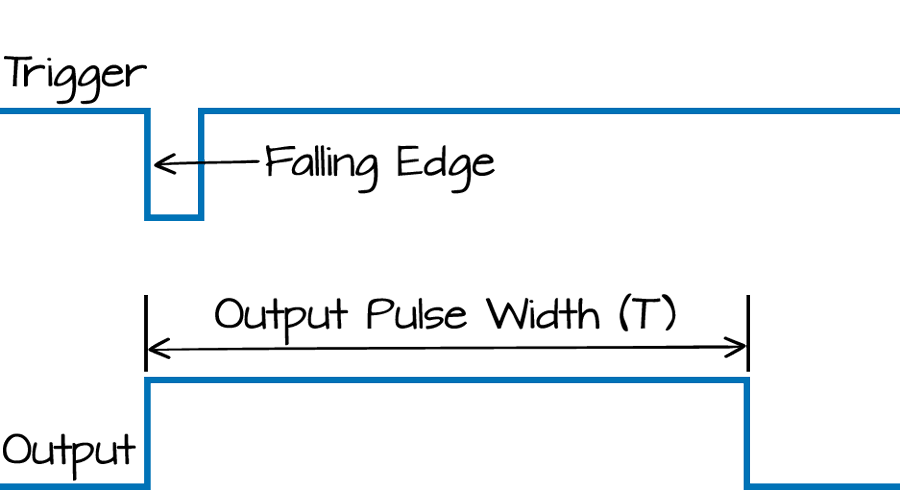
I am new to electrical engineering. I would like to make a circuit that will go to low after a short given time (lets say 0.2s) of being High. Using graphics I would like to convert this:

to this:

I am new to electrical engineering. I would like to make a circuit that will go to low after a short given time (lets say 0.2s) of being High. Using graphics I would like to convert this:
to this:
You can easily configure a 555 to generate a pulse out on power-up, as shown below.
What happens in the circuit is that when S1 is made, +5V is sent to the chip immediately, powering it up, but TRIG and THRS are held low until C1 starts charging up through R1.
TRIG being low when +5V goes high forces OUT high until C1 charges up to about 2/3 Vcc, (3.3V) then THRS being at 3.3V or higher will drive OUT low until until S1 is opened and closed again, when the cycle will repeat.
The LTspice .asc file is here if you want to play with the circuit.

It sounds like you want to build a monostable multivibrator. From the link, "A monostable produces a single pulse when triggered.". It is called 'monostable' because when the output is triggered, it is temporarily in an 'unstable' state; and decays back into a stable state (off). The decay time (e.g. the pulse length of 0.2s you suggest) is determined by the time constant of a resistor and capacitor used in the circuit construction (RC time constant).
You can buy a single IC that does this for you (e.g. the Linear LTC6993) or you can build it yourself. An example implementation of building it yourself can be found here.

In this implementation, the circuit starts out with TR2 turned on, which effectively turns off TR1 (since TR2 being on implies that the collector of TR2 [which is also 'Vout'] is at a voltage of GND + the collector-emitter saturation voltage of TR2, which might often be around 0.2-0.3V). If Vout is at 0.2 or 0.3V, this is insufficient for TR1 to turn on -- therefore, TR1 is off (e.g. no current flows through R1, into TR1 collector, and out of TR1 emitter to ground)
However, when a pulse is received at the 'trigger input', this temporarily raises the voltage at the base of TR1 enough to turn it on. Therefore, TR1 turns on temporarily, which draws current from capacitor CT, which draws current away from the base of TR2. This is because as current flows "from" of the 'positive' side of capacitor CT, an equal amount of current must flow "into" the 'negative' side of capacitor CT. Hence, the current coming from +Vcc through RT into the base of TR2 now is going into capacitor CT instead of into the base of TR2.
TR2 then turns off as a result, which then allows the voltage at Vout (the collector of TR2) to rise close to +VCC. However, once the voltage across capacitor Ct stabilizes, TR2 turns back on, and the initial state of TR2 being on and TR1 being off is resumed.