I need help confirming some hunches. I'm trying to figure out what type of circuit this is:
Any ideas?
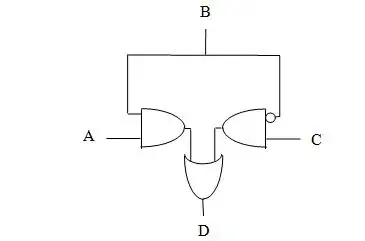
Also, I think the logic expression for this is:
D = (A AND B) OR (NOT(B) AND C)
I need help confirming some hunches. I'm trying to figure out what type of circuit this is:
Any ideas?
Also, I think the logic expression for this is:
D = (A AND B) OR (NOT(B) AND C)
There are only two intermediate signals, so it's relatively easy to break down. We'll call the left input to the bottom OR gate X and the right input Y.
I'm going to use some shorthand here - NOT = !, AND = &, OR = |.
X = A & B

Y = !B & C
Those two lead into the OR gate that produces D:
D = (A & B) | (!B & C)
Which is the result you came up with, so you are correct.
One application of this logic circuit is to act as a selector:
B is asserted, then A is output on D, and C is ignored.B is de-asserted, then C is output on D, and A is ignored.Its a 2:1 multiplexer, the select input being B. A and C are inputs, D is the output