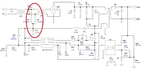
In Below SMPS Circuit ( Credit to:- NXP SMPS Design Tool ), in Red mark what is function of this resistor and why mid point of register is connected to Aux biasing of transformer.
Thanks in advance.
In Below SMPS Circuit ( Credit to:- NXP SMPS Design Tool ), in Red mark what is function of this resistor and why mid point of register is connected to Aux biasing of transformer.
Thanks in advance.
The resistors supply start-up current for the SMPS, after which the auxiliary winding of the transformer takes over. More often a single high value resistor (or two in series) are used from the output of the bridge rectifier (C6 + terminal), but this method will work too.
They also act as bleeder resistors for the 330nF filter capacitor so the user won't get shocked if they touch the plug pins after it has been unplugged.
By using two resistors in the shown configuration they make the former function more reliable and the latter less reliable (start-up resistors going open is a common failure mode of off-line switchers).
Not sure if those are the only reasons, but that's what it looks like to me.