The same chip can be run at 5v or 3.3v so it's tolerant to 5v so why when I run it at 3.3v can't I send in a 5v signal on an input pin? Curious on what's in the chip that makes this a bad idea.
Asked
Active
Viewed 3,385 times
2
-
3Probably the pin protection diodes. – Olin Lathrop Mar 08 '15 at 21:18
-
1This should explain the pitfalls of driving a 5V input with 3V logic: https://learn.sparkfun.com/tutorials/logic-levels/ttl-logic-levels Which is not what you asked but considering your question I think it will be a good read. – Wesley Lee Mar 08 '15 at 21:19
-
1I found this that explains it pretty well too: http://jeelabs.org/2010/12/16/voltage-3-3-vs-5/ – Ryan Detzel Mar 09 '15 at 12:33
4 Answers
5
This is to expand on Olin's comment about protection diodes.
The protection diode will clamp the 5V input, and it can be damaged in the process.
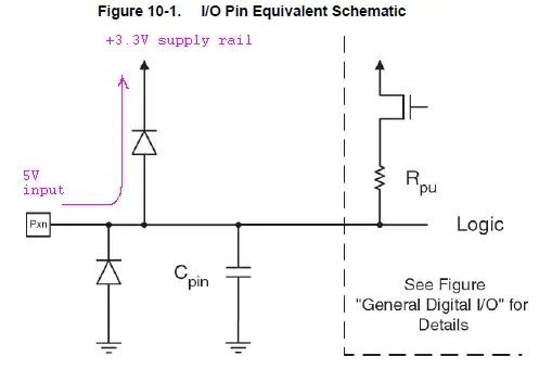
(fig. 10-1 from p.60 in the datasheet for ATmega32u4. Purple scribbles mine.)
On a different note. From the O.P.:
The same chip can be run at 5v or 3.3v, so it's tolerant to 5v [...]
[emphasis mine, N.A.]
There is a flaw in this reasoning. 5V tolerant means that an IC can use 5V input while it's powered from +3.3V (or some other voltage lower than +5V). If the IC can use a 5V input while it's powered from a +5V supply, that doesn't constitute 5V tolerance.
Nick Alexeev
- 38,181
- 17
- 100
- 237
3
It's because of the input protection diodes. Each pin has a (normally) reverse biased diode from the input to Vcc. If a high voltage spike comes in the diode conducts it to the rail instead of it damaging the actual input circuitry. If you power the chip with 3.3V a 5V input will forward bias the diode with a lot of current and damage it, then possibly the rest of the circuitry.
You can actually use this to your advantage though, put a resistor in series with the input. Then when you apply 5V the diode will turn on and clamp the voltage to a safe level, but the resistor will limit the current to something safe.
Your other option is to power the chip with 5V. The datasheet says it will accept anything over 0.6*Vcc as a logic high, so anything 3.0V or high will be read correctly. Which method is better depends on the output voltage you want.
Austin
- 1,066
- 7
- 9
-
There are similar diodes from the input to ground to protect against negative spikes, but they don't come into play here. – Austin Mar 08 '15 at 21:34
-
1
1
Look at Table 28.1 Absolute Maximum Ratings - in that table, it says
"Voltage on any Pin except RESET with respect to Ground ................................-0.5V to VCC+0.5V"
There will be protection diodes on the I/O pins that will prevent the voltage on the pin from going outside those limits. The "Vcc+0.5" limit applies regardless of Vcc.
Peter Bennett
- 59,212
- 1
- 49
- 132
-
So it might not break anything it just wont work because of those diodes? – Ryan Detzel Mar 08 '15 at 21:33
-
1If the chip Vcc is 3 volts, and you apply 5 volts to an input pin, the protection diode on that pin will try to pull the 3 volt Vcc towards 5 volts. This may destroy that diode, and/or may cause higher than expected Vcc voltages on other parts of the circuit. – Peter Bennett Mar 08 '15 at 21:38
-1
I think this is down to the board design, as I have mainly worked with Texas Instruments MSP430G series devices, you can use an internal oscillator for timing or external crystal. But have recently been working with the Arduino. The MSP430 can work with a few voltages from 3.3V to 1.8V, however the maximum clock speed is reduced with supply voltage.
In the case of the Arduino Nano for example it comes in either 5V or 3.3V, they have 2 crucial differences.
1) The RAW pin is physically connected to either a 5V or 3.3V linear voltage regulator. 2) The crystal on a 5V Nano is 16MHz and on a 3.3V Nano it's 8MHz
Ant
- 395
- 4
- 14