1

Im having trouble getting my head around using two mosfets to pass AC.

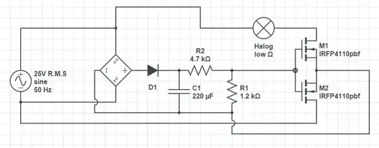
I have reduced my schematic to its bare bones to help keep it un-cluttered. The aim of this circuit is to use PWM to dim a bulb running AC. the PWM circuitry and gate drive is omitted.

I am taking 25V AC rms through a bridge rectifier to allow me to maintain a DC level at the gate through the voltage divider with the aid of a cap.

The above circuit caused my lower fet to fry and also the insulation on the wire from the source to my bridge negative terminal melted. enter image description here

Any assistance is greatly appreciated!

EDIT: I have amended the circuit to eliminate the short. enter image description here

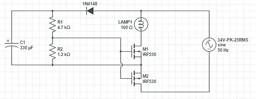
But i am unclear as to how the VGS limit of 20V is not exceeded. The output of the Divider is around 7V (more than enough for my fet). So if the top rail initially peaks at 34V and charges the cap, then the cap will hold the gates at 7V relative to the source ( and cathode of the cap). For the opposing cycle, the lower rail peaks at 34V, or relative to the top rail/capacitor -34V (i believe this is where my logic is incorrect). When the bottom fet opens up, this -34v potential is passed to the source before travelling through the body diode of the top fet to the load. if this is true, the VGS potential would be 7V (positive at the gate) + the negative 34V peak at the source passed from the drain = 41V.

I have been told in a forum elsewhere this reasoning is incorrect and a simulation proves the VGS potential to maintain at 7V. enter image description here

I do not doubt the simulation may be correct, however i am failing to prove to myself either way what is happening.

engineeroverhere
  • 63
  • 1
  • 1
  • 8

1 Answers1

2

If you think at how the bridge works, you see that it will always connect + to the AC terminal having the highest potential and - to the AC terminal with lowest potential. And let's call "ground" the lowest AC potential, the one that is connected to - of the bridge.

The source of M2 (top terminal of your M2) is therefore connected to this "ground". In the other hand both positive and negative terminals of AC power will have a potential that will be equal or above this "ground" (alternatively half cycle equal, half cycle above). But one terminal of AC power is connected to M2 drain (bottom terminal of M2).

M2 is always ON because gate to source voltage is positive, you are therefore shorting AC power through M2 during half cycle.

One way of doing it, as I can think of using MOSFET is showed in the following schematics. D1 and D2 avoids reverse conduction. M1 (an NMOS) allows conduction during positive cycle of AC and M2 (a PMOS) allows conduction during negative cycle. Also M1 only conducts if gate is positive in regards to AC bottom rail, and M2 only conducts if gate is negative in regards of AC bottom rail. Then by setting + and - as showed in the schematics the bulb would be 100% ON. By reversing + and - voltages in the gates, you would get a 0% ON.

schematic

simulate this circuit – Schematic created using CircuitLab

One other possibility using only NMOS could be this one:

schematic

simulate this circuit

By the way, R1 allows some current to flow through the bridge so that the diodes in the bridge are ON, and D1 (which is indeed necessary) disconnects the capacitor from AC when its voltage is above AC. At this moment D1 is OFF but not the diodes in the bridge so that (-) terminal is always connected to the lowest AC potential. Then the voltage divider gets about 15 V or so, if your AC voltage is 110 V, this is the "ON" signal.

During positive AC cycle, current goes from top to bottom through body diode of M3, and through M1's channel. During negative AC cycle, current goes bottom to top through body diode of M1 and through M3's channel.

This circuit idea could work, but I've maybe overlooked something. It is better to try it with a reduced voltage at first.

It is necessary also to pay attention at the absolute maximum ratings. For example when AC voltage is 100 V during positive cycle, VGS of M3 would be around -85V, its channel will be off as we expect, but the transistor will be likely destroyed! Therefore it is necessary to clip M3 "ON" signal voltage to avoid going too much negative.

Roger C.
  • 2,205
  • 1
  • 10
  • 12
  • I agree with you on the redundancy of D1, however i am

    switching the gate at 20Khz, so i am using a high frequency diode for D1, the bridge is rated for low frequencies.

    my apologies for applying the term ground incorrectly. old hobbits die hard.

    Could you recommend a better solution to this circuit? Or will a resistor from common source to the -VE bridge terminal suffice?

    Thanks for this, it has been frustrating me all day!

    – engineeroverhere Jan 23 '15 at 17:50
  • You could look at here http://electronics.stackexchange.com/questions/19250/pwm-to-vary-the-light-intensity-of-a-220v-bulb – Roger C. Jan 23 '15 at 18:05
  • i appreciate that, however i am doing this for a project so i have certain constraints. One being mosfets. Thanks! – engineeroverhere Jan 23 '15 at 18:14
  • 1
    I update my answer to provide a possible way to go! – Roger C. Jan 23 '15 at 18:42
  • Appreciated! I am trying to make this work sufficiently with the gear i have (10 of the same n-channel mosfets), though this will be my fallback. Thanks again – engineeroverhere Jan 25 '15 at 11:47
  • Actually, after some more smoking fets and wasted money. Maybe I need to listen to you sooner haha. I think ill either rectify and stick with a single fet, or i shall use a p-channel as suggested. Thanks alot! – engineeroverhere Jan 25 '15 at 13:18
  • Until parts arrive however, i will try and suss why my lower fet keeps blowing. – engineeroverhere Jan 25 '15 at 15:14
  • I've edited my answer to add a possibility using only N-channel MOSFETs. Hopefully it will work! – Roger C. Jan 25 '15 at 17:00
  • I really do appreciate the help! I managed to get two n-channels to work by using a battery to control the gate. I can see from your circuit the sources are connected to the AC lines with the drains common to the load. With a DC level held at the gate by the voltage divider, wouldnt the Vgs voltage = 0 when the voltage of the line is = to the DC level? Then it would be a negative potential for the rest of the ac cycle. Thanks again! – engineeroverhere Jan 25 '15 at 17:29
  • No, this DC level is always relative to the AC rail with lowest potential (thanks to the bridge). During half cycle, the AC rail with lowest potential is the bottom one, and during the other half cycle, the AC rail with lowest potential is the top one. The DC level is always above the lowest potential (let say 15 V above). If we plot VGS of M1 it should then be equal to 15 V during half cycle, and during the other half cycle it would decrease until become negative (and will peak somewhere at -135 V or so, that why it must be clipped somehow) and then will increase again. – Roger C. Jan 25 '15 at 18:19
  • Just re-read this with a fresh brain this morning. I can see the VGS issue and my fets will indeed fry. they can tolerate a 20V potential. My supply is 34v peak so i would expect a maximum VGS difference of - 44v. How on earth can i go about clipping it? why isnt life easy! haha

    THanks!

    – engineeroverhere Jan 26 '15 at 10:22
  • Actually if your supply is 34 V peak, you would expect a maximum of 15-34=-19 V (considering that 15 V is the voltage after the divider). So it might work :-). Clipping is rather simple with a diode and a resistor, you can see here how: http://www.electronics-tutorials.ws/diode/diode-clipping-circuits.html . There is a drawback however, you might want to put a big resistor because during half cycle a big voltage will drop on it. But a big resistor means it will take longer for the switch to go ON from OFF (and viceversa), and this can also lead to MOSFET destruction! – Roger C. Jan 26 '15 at 11:11
  • Update the initial post. Thanks again Roger. – engineeroverhere Jan 27 '15 at 18:32