4

I'm trying to create a MOSFET based switch device. I want to control the gate with some GPIO pins (H = 3.3V, L = 0V). I understand there must be a positive voltage (VGSth) between gate and source in order current can flow from drain to source.

schematic

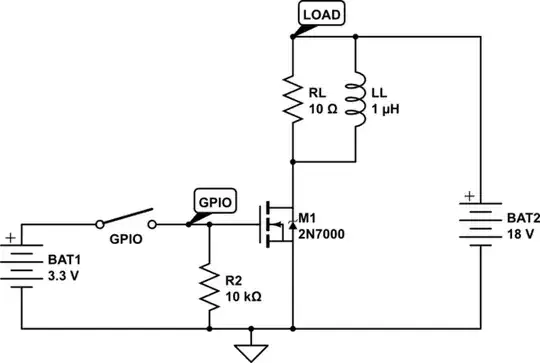
simulate this circuit – Schematic created using CircuitLab

My Question is, can there be different voltage sources like in my schwematic with common ground? As I understand, R2 only restricts the current flowing from GPIO to GROUND since there is almost now current flow between Gate and source because of it almost infinite impedance. If this assumption is correct, can't be R2 have an almost inifinite impedance too like 10M ohms?

The purpose is, that I wand to provide an external power source BT2 that can provide far more current than BAT1 power source.

Is there something I'm missing in order to work?

bkausbk
  • 288
  • 5
  • 16
  • For information: PSMN3R3-60PL seems to be a VERY good N-Channel power mosfet that is able to work optimal with 3.3V logic. I_D > 240 A @ V_GS>=3.3V and V_DS>=3.3V with R_DS(ON) < 5mOhm. – bkausbk Feb 02 '15 at 14:33

1 Answers1

5
  • can there be different voltage sources like in my schwematic with common ground?

Absolutely. Only the voltage difference between the source and the gate counts for turning on the transistor; anything else can be a free-for-all as long as the circuit makes sense.

  • As I understand, R2 only restricts the current flowing from GPIO to GROUND

Incorrect. R2 allows the gate to drain once there is no voltage applied to the gate, since the gate of a MOSFET acts as a capacitance. Without R2 the transistor would take many, many orders of magnitude longer to turn off since only the leakage current could drain the gate capacitance, assuming a switch as shown in the schematic. Actual GPIO outputs are usually push-pull, and hence both source and sink current, so R2 wouldn't be required at all were one being used.

How large R2 should be depends on both the current available from the supply connected to the gate as well as the desired turn-on and turn-off times; the larger R2 is, the weaker the supply can be, the faster the turn-on time will be, and the slower the turn-off time will be.

Ignacio Vazquez-Abrams
  • 48,488
  • 4
  • 73
  • 103
  • 1
    You are correct by saying that a gpio is a push/pull usually so R2 doesn't effect the turn off/on time. R2 is there for the split second when the gpio is not a push/pull and is in high z mode (when booting, for example). The gate could easily gather charge and activate the mosfet. In this case R2 will discharge the gate. – Mike Jan 14 '15 at 06:34