I am a beginner in Electronics and I am not able to understand why do we need to put this resistor(Resistor which comes after the switch) in this schematic? Does it save IC from current? but how ? Thanks
I am a beginner in Electronics and I am not able to understand why do we need to put this resistor(Resistor which comes after the switch) in this schematic? Does it save IC from current? but how ? Thanks
I originally thought you were asking about this resistor. I'm leaving the explanation here since it might be useful anyway.
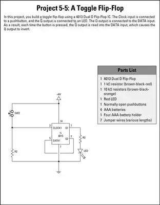
The point of this circuit is to let you get some intuition about flip-flops. To do that, the LED is hooked up so that it lights when the flip-flop output is in the high state.
However, the output of the flip-flop tries to be a voltage source, which is a bad match for driving the LED. It's also at the wrong voltage anyway. The resistor drops the voltage between the flip-flop output and the LED's on voltage, while letting a predictable amount of current flow in the process.
Let's say the flip-flop is powered from 5 V, that you want to put 5 mA thru the LED when the output is high, and that the LED is a common green type that will drop about 2.1 V when on. That means the resistor will have 5.0 V - 2.1 V = 2.9 V across it. We already said it needs to allow 5 mA thru it in that case. From Ohms law, 2.9 V / 5 mA = 580 Ω. The standard value of 560 Ω is close enough and should work fine, as long as the flip-flop output can source the 5 mA. Many digital outputs can do that, but not all, so you have to check. If the flip-flop can't source enough current to drive the LED to sufficient brightness, you can use a transistor in between.
I see now you asked about the other resistor, the one that is connected to the switch. That's a pulldown resistor. It makes the flip-flop input reliably go to the low state when the switch is not pressed. It's value is a compromise between pulling the input hard enough low when the switch is off, but not requiring too much current thru the switch when it is pressed.
I go into a lot more detail about pullup (same thing, just the switch and resistor flipped) resistors at https://electronics.stackexchange.com/a/23647/4512.
The resistor is called a pull-down resistor. If it were not there, when the switch is open there would be no defined voltage on the pin the switch is connected to. This is called a "floating" input and generally does not guarantee that the input is in one state or the other. By adding the resistor we know that the input will be low when the switch is open.
If there would be just a wire from the switch to ground and not a resistor, the switch would short-circuit the positive voltage and ground and nothing good would come of it.
On the other hand, if there would be nothing (no wire and no resistor) from the switch to ground, there wouldn't ever be a reliable low level in the clock input.
The resistor 'pulls' the input down to ground (LOW or logic '0'). When the switch is closed there will be a positive voltage at the input (HIGH or logic '1'). When it is released the input goes back to ground.
With the switch not pressed, and the resistor removed (replaced by an 'open'), the input would not be connected to anything. With modern CMOS chips, that will result in the input picking up stray signals, often the over-present 50/60 Hz 'hum'. That is not what you want!
As PkP explains, replacing the resistor with a short (wire) is not a good alterntive iether.
In short this make assurance that we should have standard logic "1" when button is pressed and "0" otherwise. In this case we are sure about the digital output. Being Flip-Flop output should be only logic "0" or "1" and nothing between them ! It's the best solution for making only two possibilities in output (Input also).
– Tchaps Nov 23 '14 at 23:50