Spice originally started with ascii type files (or text type files) describing connections between components - these are still the bottom line file used by all spice simulators I believe. Here's an example: -
And is described by the following text: -
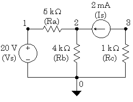
Example_1 EXMPL01.CIR
Vs   1   0   DC   20.0V ; note the node placements
Ra   1   2   5.0k
Rb   2   0   4.0k
Rc   3   0   1.0k
Is   3   2   DC   2.0mA ; note the node placements
.END
As can be seen, Vs is described on the 1st main line as connected between node 1 and node 2, having a DC value and that value is 20V. Note the node numbers on the schematic and note that all 5 components in the circuit have a line with node connections. Node zero is the default for 0V/Earth.
Like I said in my comment, any circuit/schematic front-end still converts the circuit you draw to a file like this meaning, you can export the ascii/text file and more than likely, import it into another spice software package. However, it probably won't back-engineer some kind of schematic for your convenience. This would be asking too much I expect!!
Here is where I got the example from and it looks nice and easy for a learning tutorial. It should get you started on the nuts and bolts.
BTW, when I first started using spice (mid 90s) this is all realistically anyone got when buying software - the ability to "code" the nodes with text and usually a large file of compoent definitions.