Can anyone please simply explain to me what it is? A simple little lesson or answer would be appreciated.
-
1A specific circuit that you are having trouble understanding might help to answer this question. – Null Oct 29 '14 at 04:08
3 Answers
Bubble Pushing(or Bubble-to-bubble convention/ Bubble Matching)
I'm not sure if this what you are referring to, but that's what googling 'bubble pushing' yielded. I've personally never heard this term before.
Bubble pushing is a technique to apply De Morgan's theorem directly to the logic diagram.
Change the logic gate (AND to OR and OR to AND).
Add bubbles to the inputs and outputs where there were none, and remove the original bubbles.
Logic gates can be De Morganized so that bubbles appear on inputs or outputs in order to satisfy signal conditions rather than specific logic functions. An active-low signal should be connected to a bubble on the input of a logic gate.
According to this, it's just a visual way of performing de Morgan's theorem vs doing it on paper with boolean algebra.
- 109
- 5
- 11,955
- 10
- 57
- 104
The bubble-to-bubble convention and bubble matching can help us understand the behaviour of a logic gate circuit better.
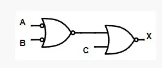
For example, take a look at this logic circuit first. Let's say you want to know which combination of inputs A,B,C will make the output X be 0 or 1.

Obviously, this figure doesn't comply with the bubble-to-bubble matching convention. So, you may find it a bit hard to tell its behaviour.
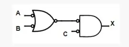
However, after you make this figure comply to bubble-to-bubble matching convention (as shown below). You will find it easier to tell the input combination to make output X to be 1. That's C=0 at the same time either A=0 or B=0.

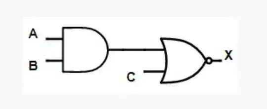
After dealing with the 1 situation, let's move on to the 0 situation. Let's do the bubble-pushing again, by DeMorgan's Theorem, you will get the circuit below.
 Now, obviously, you can easily tell that the output
 X=0 when both A=1 and B=1 or C=1.
In summary, making a logic gate circuit comply bubble-to-bubble matching convention can make it easier for you to know how the circuit behaves.
A small tip here: After you have done the bubble-to-bubble matching, you can say '0' when there is a bubble, otherwise say '1'.
- 168
- 1
- 8
This is just a graphical way of expressing the "Break the line and change the sign" expression used to simplify logic statements, by changing an AND expression to OR and vice versa. If you review sum of products, products of sums, and simplification by Demorgan equivalence, that will cover all the background theory behind this graphical approach to simplifying an expression. A reference is http://www.amazon.com/Schaums-Outline-Boolean-Switching-Circuits/dp/0070414602
- 545
- 3
- 14