I've seen this in a bunch of ATMega / Arduino reference designs:
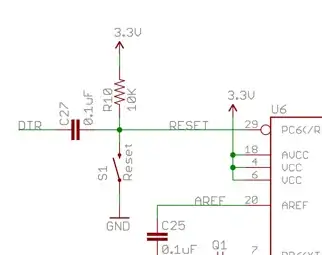
The RESET pin is pulled up high with R10, pulled low with a switch (S1), but then tied to the DTR line from a UART breakout via C27 - a small capacitor. This last bit is how the Arduino bootloader triggers the reset, but what's actually happening here? How does DTR going low translate to the pin triggering?