6

I've got a simple triac phase angle controller which is very similar to the MOC3021 data sheet app circuit. Most of the time everything is fine. The circuit looks like this: standard MOC3021 circuit from Fairchild datasheet

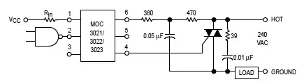
The triac is a BTA06-600B (ie standard sensitivity, not snubberless). The opto snubber circuit is the same, the triac snubber circuit has a 0.015uF cap and 270R resistor.

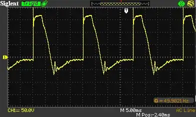
I've got a problem always occurs when the triac gets to about 75C - it turns on all by itself with a distored asymetrical waveform like below - turning on for part of one half of each cycle. This generates a waveform that the connected motor doesn't like at all - and it seems to stay there forever until the motor burns out.

Asymetrical waveform with no gate drive

Once it cools down a bit it turns back off. The load doesn't seem to matter - it happens with a 30W fan or a 4A fan.

There is no gate drive - I've tried shorting out pins 1/2 on the Opto but it makes no difference. Also, when I heat up the triac the opto isn't getting warm - and I can cause the problem to appear with heat.

I can make the problem occur by heating the triac with a hot air gun though I don't think that is the only cause - it happened this morning a few times without much heat but we then spent hours trying to replicate the output with no success.

In the field this "other" cause is what is happening to some units - the triac shouldn't get to anywhere near 75C in normal operation as it is driving a 50W/0.22A fan and is mounted on a heatsink.

Why does the triac turn on by itself?

[update 1] It seems the problem is restricted to some triacs - I pulled some more units off the shelf and they were ok with the heatsink > 100C (110C according to my multimeter and sizzling hot according to my wet finger!). The one that worked was a different date code.

[update 2] The high temperature testing was done with a hot air gun not from the load/lack of heatsinking. In normal operation it is dissipating about 0.022W and is mounted on a heatsink. I've been hitting it with spray freeze & a hot air gun trying to make it misbehave.

[update 3] I have tried 1k, 470R, 270R between the gate and A1 - makes no difference.

[update 4] I'm not sure it is dv/dt - the load is "off" (ie opto not driven) then when I heat up the triac it turns on by itself and stays on until it cools down again

[update 5] I know the 110C/etc temp is hot - perhaps too hot. My point with that comment is that even at that temperature some units are ok while at a temperature much lower than that others are not. The faulty one "fails" at something like 70C while the good ones are ok at 110C

[update 6] I have concluded that there is just something wrong with this particular triac - I've tried to replicate the problem with a heap of other units and can't. Asmyldof - it's not the spike causing the problem because the triac can be off, heated and then the problem occurs - ie the heating is causing the odd waveform, not any motor spikes.

peter_mcc
  • 191
  • 1
  • 8
  • How did you measure the temperature and did you use a heat sink? – jippie Sep 17 '14 at 05:58
  • Measured it using a thermocouple and a multimeter. It also didn't sizzle when I touched the heatsink with a wet finger. It's clipped onto a small heatsink but for testing I'm using an adjustable heat gun to make it hot. – peter_mcc Sep 17 '14 at 06:19
  • A proper direct link to both data sheets would please the lazy – Andy aka Sep 17 '14 at 09:05
  • 1
    110°C at the heat sink doesn't sound too healthy for a silicon based semiconductor – jippie Sep 17 '14 at 09:18
  • Added links to both datasheets. Clarified that the high temperatures were done with a hot air gun. They are rated for operation at up to 125C or 6A at 105C so it wasn't too unreasonable. The important point is that the second and third units didn't play up even though the triac temperature was a lot higher than the failing one. – peter_mcc Sep 17 '14 at 11:55
  • Try a resistor (1k ohm or as low as 330 ohm) from the gate of your triac to A1 (the triac pin that is connecting to the load). This is often done to improve noise immunity by reducing gate sensitivity. Keep the leads short and as close to the triac as possible. – Tut Sep 17 '14 at 12:31
  • I see you are in Australia. We implemented the above (along with a snubber that you already have) to fix a similar problem that was only occurring with units in Australia ... I'm not sure why. Units in Europe were working fine. – Tut Sep 17 '14 at 12:51
  • What kind of load exactly are you switching? If it's an inductive load then dv/dt is probably your problem. – Spehro Pefhany Sep 17 '14 at 14:30
  • The 125°C spec is for the junction temperature (the internal chip). The junction temperature will be higher than the temperature of the case, which in turn is higher than the temperature of your heat sink. – jippie Sep 17 '14 at 20:22
  • I've added some more updates above. It has a snubber, I've tried down to a 270R resistor between the gate and A1 with no effect, I don't think it's dv/dt because the triac turns on by itself with no drive to the opto - just 75C heat on the triac. The 110C temp is coming from "outside" the triac via hot air blower - not inside - so the juction temp is probably lower. In any case, some units are ok at 110C while others fail at 75C or less. – peter_mcc Sep 17 '14 at 20:33
  • I'm trying to get more failed units to see if the same pattern repeats itself – peter_mcc Sep 17 '14 at 20:34
  • How close is the moc3021 to the heat source as you warm it up? I ask ask that has an operating temp of 85C. Now I remember an IGBT driver I designed years ago using a 105C opto BUT it would randomly stop driving (thank god for an additional inversion..). The problem was the Vce sat of the output photo transistor was raising and at 80c it's low was above a 74HC14 Schmitt low = it would never transition –  Sep 17 '14 at 21:04
  • JonRB - It's a few cm away - I don't think that's it because the "good" ones work at higher temps than the "bad" one. – peter_mcc Sep 18 '14 at 14:33
  • I would like very much to see two more plots, if you can: 1. the same as above, but zoomed out, so that the initial spike does not go off screen. 2. A plot like the one you have above, but showing the original mains voltage on a second channel. Possibly the spike is caused by motor/snubber interaction and causing a premature breakdown? – Asmyldof Sep 22 '14 at 16:38

2 Answers2

1

I see two issues with what you're trying to achieve: 1. I assume you want to control the speed of the motor by adjusting the firing angle of the triac. AC motors do not respond well to lowering the RMS voltage applied to them which happens when you delay the firing angle. When a motor is operated at less than its rated voltage, it compensates by drawing more current to maintain its mechanical power output. I'm not surprised the motor burns out. If you want to control the speed of the motor, you need to use a variable speed drive which varies the frequency of AC to the motor. 2. The graph shows what looks like a spike at the leading edge of each waveform. If you expand the timebase, you'll likely see it better. Check its amplitude. The triac heats up because it's switching on/off every cycle. The more frequent the triac switches, the hotter it gets. It is during the switching transient from off to on or on to off that the triac consumes power, albeit for a short interval of time. When it fully on or fully off, it dissipates very little power. During these switching states from off to on, the motor delivers a voltage spike that likely exceeds the forward voltage of the triac and causes it to turn on despite the snubber network. If you exceed a triacs forward voltage it will turn on even without gate drive. The collapsing magnetic circuit of the motor is generating a voltage spike that retriggers the triac. I suspect the threshold lowers with rising temperature. I think the circuit will work OK for simply turning on or off the motor for long periods of time (when the triac's not constantly switching) but don't try using it to change motor speed by varying phase angle.

Matthew
  • 66
  • 2
  • Hi Matthew, thanks for the comments. 1) yes, I do want to control the speed of a motor by adjusting the firing angle. Whilst not perfect the technique does work for some applications and has been successfully used for many years. If you read my question more carefully the motor is burning out because of the distorted waveform shown - not because of the phase angle speed control. Using a variable frequency drive with a small single phase motor has its own challenges as they are often not designed for it. – peter_mcc Oct 12 '14 at 13:25
  • (cont) 2) the graph shows a highly asymmetrical waveform which effectively delivers AC + DC to the motor. As I tried to explain, this waveform happens when there is no gate drive if the triac is heated up. As in - motor/triac is off, heat up triac, get waveform shown. I don't think it is excessive forward voltage of the triac causing the problem because it occurs without the motor running (ie no voltage spikes). Since the problem happens with a 30W fan (ie about 0.2A) the heating effects from the load are very small - its on a heatsink and doesn't even get warm. – peter_mcc Oct 12 '14 at 13:32
1

I think I've decided that I just have a faulty triac. I've tried to replicate the fault on many other units and cannot, no matter how hard I try.

Thanks everyone for your help - your comments made me think hard about what was going on.

peter_mcc
  • 191
  • 1
  • 8