5

I have an 220V air compressor (30A) in the attic of my garage.

It has a 110V automatic drain valve connected to it.

A the breaker box downstairs I want to be able to turn the power off to BOTH.

Ideally I could simply turn off the 220V circuit (the compressor is the only load).

The 220V circuit is single phase and the receptacle is a NEMA 14-50.

It is my understanding that this is a split-phase 3-wire system. It's really 4-wires: Ground, Neutral, Leg 1 (110V), Leg 2 (110V).

What I want to know is if there is any problem with me using one of the two legs (plus ground & neutral) to power a 110V outlet for the automatic drain valve. I'm 99% sure there's no technical problem. I just want to double check on any safety issue or something I may not be aware of (as a DIY).

Kevin Vermeer
  • 20,067
  • 8
  • 57
  • 102
tig
  • 231
  • 1
  • 2
  • 10
  • 1
    Putting this in a comment because I'm not sure, but you should be fine. AFAIK most houses get one of these split phase lines, and all 120V circuits are powered in this way (one of the legs). – Billy ONeal Mar 22 '11 at 06:00
  • 1
    what's your location? Since you referenced NEMA, I'm guessing that you're in the US, right? – Kevin Vermeer Mar 22 '11 at 12:44
  • Will the valve need substantial current? – jpc Mar 22 '11 at 20:55
  • 1
    Safety-wise the main issue is the overcurrent protection. You shouldn't be putting a 15A outlet on a 60A circuit. – Peter Green Jan 08 '17 at 02:36

6 Answers6

4

Since I'm loosing confidence in the idea of using the single relay to control both circuits, I now think the right answer is to simply buy ANOTHER RELAY. I can get a less expensive 110v capable relay for the drain-valve circuit and wire them both to the same 24V signal from my digital IO controller.

This keeps all of the line voltage stuff "clean" and normal.

I'm not sure why I didn't think of this before.

[EDIT: 12pm 3/27] I'm 90% finished with constructing this thing. One more trip to the hardware store and the use of a my toner to find the 24v wire in the attic and it should be up and running. Here's a pic of the two pump-start relays mounted and mostly wired: enter image description here

[EDIT: 7pm 3/27] Done! Works like a champ. Here are some pictures of the final result: enter image description here

enter image description here

tig
  • 231
  • 1
  • 2
  • 10
3

I broke this up into two different questions.

1. Is it technically possible to get 110V AC by splitting a three-phase 220V AC system?

The answer to question one is "Yes". It's perfectly possible. Every other 110V circuit in your house is powered by splitting this same three-phase 220V AC into sub-circuits. If you look at your panel, the circuit breakers are arrayed like this (Yay for ASCII art!)

Leg 1       Leg 2
|-------    |
|    -------|
|-------    |
|    -------|
|-------    |
|    -------|
|-------    |
|    -------|

A 220V circuit simply bridges two of those breaker spaces. A 110V circuit uses just one of them. You're proposing to do this in a separate location.

2. Are there any problems with splitting a three-phase 220V AC system?

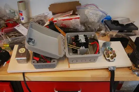
The only safety issue that I can foresee is that a short circuit in your 110V automatic drain valve wiring may not trigger the circuit breaker properly. I'm not familiar with how a 220V breaker works, but you're using it in a non-standard way: it will be loaded unevenly. It's entirely possible for one leg of the 220V line to become shorted and not the other, so the designers of the breaker should have planned for this.

The other issue which hasn't been mentioned yet is the legal issue. You'll need to talk to an inspector or electrician to verify whether this procedure is legal or not. My copy of Wiring Simplified (which is a great resource for a DIY electrician, but doesn't cover edge cases like this very well) doesn't mention it, but you can read the National Electrical Code online for free and see if there's anything about that question. My guess is that they'll want you to run a sub-panel into your garage, and use separate breakers for your 220V compressor and your 110V automatic drain valve. That's significantly more expensive than an extra outlet in the attic, but it might be worth it to be compliant with the code and to not have to trek through the house every time you blow a circuit in the garage...

One last thing: Why do you need to turn the automatic drain valve off when you shut down the compressor? Depending on the valve you are using, the energy savings will probably be less than the cost of the extra outlet, and it will certainly be less than the cost of a failed inspection! Alternatively, you could use a float-controlled drain valve, which doesn't require electricity. There are other ways to do this!

Kevin Vermeer
  • 20,067
  • 8
  • 57
  • 102
  • My electrician will be here later this week for something else and I am going to ask him. I really don't want to PAY him for this job :-). The point on the circuit breaker is right on, i think.

    I might be able to put a 20a breaker in the attic. That's what I'm going to ask him about.

    – tig Mar 22 '11 at 15:23
  • On your question: The automatic drain valve will eventually release all pressure from the tank. I'd rather keep it charged so I don't have to wait for the tank to come up to pressure when I need to use it. – tig Mar 22 '11 at 15:24
  • @tig - A drain valve shouldn't release pressure from the tank when the compressor isn't cycling. I suspect that you've either created a slow leak when installing it, or there's a slow leak in your air lines elsewhere. – Kevin Vermeer Mar 22 '11 at 16:15
  • @reemrevnivek - it's an electric powered auto drain valve that opens on a timer. – tig Mar 22 '11 at 22:01
  • I thought code (in the US) was that 220 circuits could only have one outlet. – tooshel Mar 28 '11 at 16:11
  • @tooshel - You may be correct, but this is a 110 V circuit we're creating here. If you want to get technical, it's 1.5 outlets, but we're working with integer math here, right? :) Those complexities are why I said You'll need to talk to an inspector or electrician. – Kevin Vermeer Mar 28 '11 at 16:34
  • hey KV, technical problem here: split phase three-wire != split three phase. – JustJeff Jan 01 '12 at 15:34
  • @JustJeff - The ground isn't used to carry current, it's just for safety's sake, so they're essentially the same - Or am I missing something? – Kevin Vermeer Jan 01 '12 at 18:23
2

There is really no problem in using only one of the phases in orded to make a lower voltage.

I'd live in Brazil and most of the residential systems here make use of this split in order to obtain 127(v). Here we have an three-phase system which the voltage between phases is 220 and the voltage between one phase and one neutral is 220/sqrt(3) = 127 ( http://en.wikipedia.org/wiki/Three-phase_power#Single-phase_loads ).

When the system is a 2-phase system (as in center tap transformers) the phase-phase voltage is 220 and the phase-neutral voltage is half of the main voltage, in the case 220/2 = 110;

Some warnings before making the connection

1) Use an multimeter to assure that your phase-neutral voltage is 110 (v) and not 127. Even if the voltage comes to be 127 (as in Brazil) some equipments are capable to work with it.

2) Make sure that the main switch and the wires can hold both equipments current. The info about wires x current can be found here: http://www.powerstream.com/Wire_Size.htm

RMAAlmeida
  • 2,007
  • 16
  • 24
2

I realize this is an older post, but hopefully you are still monitoring responses. Your Electrician is WRONG!!! Just because a circuit will electrically, initially work, does not make it correct! What he suggests, is wrong and against code! There are reasons that a 220 volt contactor (relay) is designed to interrupt both legs.

  • It is an NEC code violation.
  • It is dangerous, there will be voltage feeding the compressor when it is expected not to.
  • The contactor is designed to interrupt its rated current as designed with both poles breaking at the same time! In affect you have derated the contactor by at least 50% of its rating, causing it to possibly fail on overload and may even hang fire!

Also your 110Volt outlet, if fused (or breaker) for 20 Amps as you say, should be a 20A recepticle, not the 15A you show in the picture. Where is the 20A fuse for that 110 Volt circuit? How much current is drawn fron the 110 Volt load? Is it so big that you need a 20A circuit? If so, you are drawing to much current and need to run a sub panel! Will 15A do? A 15A breaker can be used to 80% of its rating (12A) and should be used if less that that. If the 110 Volt load is small (1-2A) you could take it from one pole, but wire the compressor load to both poles. The 110 volt from the contactor to the fuse connection needs to be sized for the main breaker, at 30A #10 wire minimum. The other side of the fuse (load) can be sized for the fuse size, 15A # 14 wire. A small offset of current like that should not be a problem. If the load is larger, it will require a sub panel with a new feed to the compressor area. You should post a schematic of your setup, or consult an experienced electrician (or EE). The information I have given here is for the US, NEC code requirements for my area. Your codes may differ in your area, or have changed. It is your responsibility to check code requirements, I offer this information as a general guideline only.

SteveR
  • 1,622
  • 9
  • 12
  • Thanks Steve. As I indicated above, I ended up going a different route: I am using two independent pump-start relays. One is connected to a 110v circuit and controls the drain. The other is connected to the 220v circuit and controls the compressor. Nice and clean and to code. – tig Jan 02 '12 at 22:43
1

I bought a single wide mobile home to work out of in Phx. Several of the units including mine had a handyman "double lugged" the A/C disconnect to power the 220 dryer outlet to the laundry room in conduit 30 feet away in a aluminum shed, where he next pig-tailed the 110v washer and lighting to the same circuit.

My first day of ownership I removed the entire circuit and have since put a new dedicated sub-panel in the laundry room not attached to the a/c. While something will work, code means "minimum safety level." The question is how can I install "above code"? The neutral wire on the lighting circuit was wire nutted to the bare ground wire ... all connected to the 50 amp AC circuit.

If you could put on glasses that could see electrical current, you would see 50 amp current seeking a path to ground on all metal grounded surfaces.

A deadly recipe for stray current with zero GFCI or AFCI protection, combined with a wet location.

Having a history as a DIY landlord, I know what it's like to have a tenant move the breakers around in the panel trying to fix a melted neutral wire nut in a lighting circuit.

Imagine having to kill that circuit for maintenance or for an electrical fire - where do you find the hidden breaker to de-energize the circuit? Trust me, it will happen when you are tired or when you have a maintenance worker or relative who is not familiar with your creative wiring.

Jim
  • 11
  • 2
0

Spoke with my electrician and described my plan above. He agreed it would work (with the addition of a 20a breaker for the 110v leg). He thought that if there were a constant & relatively high load on the 110v leg it might cause an imbalance, but given the infrequent and small load of the auto drain valve it would work.

However, he had an even better suggestion.

The Hunter pump-start relay I purchased switches two lines. It is intended to switch the two legs of a 220v circuit.

His idea is to NOT run the pump start relay off one of the 220v legs, but instead leave it powered by the 110v circuit it is currently on. ... And to use one of the relay terminals for the 110v to the auto-drain and one for ONE of the legs of the 220v to the compressor!

This is brilliant and simple (and works because the compressor does not use neutral, only ground).

tig
  • 231
  • 1
  • 2
  • 10
  • Went to bed pondering the idea of using the two relay legs to switch the 110v drain-valve circuit AND one of the 110v legs from the compressor circuit.

    What bugs me about that is that the compressor will be getting 110v on on of the legs and 0v on the other. If it tries to start it will...try to start... and that means that the windings in the motor for the "live" leg will energize while the other half wont. It will sit there for maybe months just like that. Does not seem healthy to me at all. Even though my electrician and his "industrial equipment" expert assure me it's not a problem.

    – tig Mar 25 '11 at 15:30