2

Trying to make second circuit.

enter image description here

Here is my outputs enter image description here
(source: cs608722.vk.me)

In1+ connected to ground, OUT1 blue and after diode red

In1+ signal red and Out2 blue enter image description here
(source: cs608722.vk.me)

Why cap charges if there is no signal.. Capacitor is 0.1uF Plot's data is from Arduino, 5V-1023 0V-0 LM324 supply from arduino +5V and 0V

Glorfindel
  • 1,245
  • 3
  • 15
  • 20
a_vasilkov
  • 303
  • 1
  • 3
  • 16

2 Answers2

5

What is your time scale? For peak detectors with any but the shortest hold times, I use FET input op-amps (hold times on the order of a second or more if you do everything right). Otherwise the bias currents will produce what you see. You can use a pot and add a small value to one of the inputs to zero the offset on an LM324. Or use a much bigger cap and an emitter follower before the cap to get higher current and fast charging. In precision circuits, use a polypropylene low leakage cap.

schematic

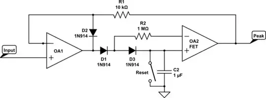
May need some capacitance across D2 for stability. Select C for speed.

(Are you really getting advice from that guy who spends 20 minutes testing design software without using any docs?)

C. Towne Springer
  • 2,196
  • 12
  • 14
  • 1ms between signals and 2ms between readings Serial.println(analogRead(A0)); delay(1); Serial.println(analogRead(A1)); delay(2); – a_vasilkov May 31 '14 at 05:10
  • @a_vasilkov Doesn't your code give a 3ms total delay between readings? Either way, your plot is a couple seconds long and an LM324 peak detect (or an integrator - which is what it is doing while waiting. You just need it to be integrating zero.) will definitely ramp to max + or - in that time frame without compensation. – C. Towne Springer May 31 '14 at 05:48
  • So what do I do if there is no signal like 1-10 mins and then it start. Oh! guess somehow I should connect cap to ground while signal is zero.. and maybe you know how to get cap signal to 5V? If I apply 0-7V to amp and arduino can read only 5V max signal.. I will fry it :( – a_vasilkov May 31 '14 at 05:56
  • @a_vasilkov Yes, you need an analog switch or FET to short the cap to ground for reset or when you know there is no signal to track. Safest I think to reset when needed rather than keep shorted. You need a "rail-to-rail" op-amp and the LM324 is not. It will not get near the 5V on output. Here is a list from Analog Devices http://www.analog.com/en/precision-op-amps/precision-rail-to-rail-amplifiers/products/index.html You can look through them for a dual package and single supply. TI also has great op-amp. Just search "rail-to-rail op-amp". – C. Towne Springer May 31 '14 at 06:08
  • There are definitely better peak-detector circuits that use two op-amps. If I knew how everyone was drawing schematics I could post one. – C. Towne Springer May 31 '14 at 06:10
  • Guess the best option will be just using Attiny85 that I have, lol, and do peak's detection and counting there and send it to arduino when needed. – a_vasilkov May 31 '14 at 06:22
  • @C.TowneSpringer - If you look above the Your Answer box, you will see a bunch of icons. Hover your mouse over each one to get a description. Starting from the left, the seventh one is Schematic. Click that and you will get a simple schematic editor. Also ctrl-w will do the trick. – WhatRoughBeast May 31 '14 at 11:01
3

The capacitor charges because the LM324 inputs have a small current flowing out of the, called the bias current. All op-amps have some bias current, but the LM 324 has more than most.

It's typically about 20nA, so a 100nF cap will charge about +0.2V/second.

Spehro Pefhany
  • 397,265
  • 22
  • 337
  • 893
  • Ok, thanks. Maybe there is some workaround? and why max charge is not 5V? Should I supply 0-7V? – a_vasilkov May 31 '14 at 04:57
  • How do you want it to behave? The circuit has no reset so the output voltage will always increase. You could use a much larger capacitor which would slow the rise. – Spehro Pefhany May 31 '14 at 05:01
  • @a_vasilkov - If you look at the data sheet for the LM324, http://www.ti.com/lit/ds/symlink/lm324.pdf, page 4 has electrical specifications. Fifth item down is Voh, high level output voltage. Note that, for mA current output, a 5 volt supply will provide no more than 3.5 volts. As the capacitor approaches peak voltage you will need less current, so the 324 can actually go a little higher, but still. And there is also the diode drop to consider. I did tell you that you need a couple of volts extra for a 5 volt signal, remember? – WhatRoughBeast May 31 '14 at 11:15
  • 1
    The simplest workaround is to change the opamp. Replacing the LM324 with a TL084 will cut bias currents to 30 pA, and your voltage rise will be about 1000 less. But you still need a reset function. – WhatRoughBeast Jun 01 '14 at 14:16