14

this is my first question and I am very much a beginner in electronics so I apologize if this is a too stupid question.

I have Atari punk console and another small homemade audiomaking circuit. These two have mono audio signals as outputs and I would like to combine these as one in the simplest possible way. I know next to nothing about audio processing but I believe that the strength of the two signals is roughly the same.

What would a neat solution be? It would be really nice if I could extend the solution later on to more than just two signals but thats not really important.

Any hints, references, guides, links or ideas would be highly appreciated.

Jonas
  • 381
  • 1
  • 2
  • 6

2 Answers2

20

The simplest way to combine two signals is with two resistors as shown in the circuit diagram below.

schematic

simulate this circuit – Schematic created using CircuitLab

The ground connecton is shared between both inputs and output. The quality can be improved by adding an output buffer (opamp), but that complicates things in requiring an IC, power supply, (de)coupling caps, ...

schematic

simulate this circuit

The advantage of the lower circuit is that the inputs see a constant input impedance, one that doesn't change with the other signal's level. This improves output quality. Practically speaking the inverting output (-) of the amplifier is virtual ground, which means it is set at a static voltage (4.5V in this case). The series capacitors are required to decouple the DC bias of both in- and outputs, they allow the signal to pass, but block the DC voltage.

jippie
  • 33,221
  • 16
  • 95
  • 161
  • 2
    Circuit 1 could be improved by connecting the 2 sources to the ends of a linear 10k pot, with the output taken from the wiper. "Similar" audio levels often aren't as close as you'd like and this would allow balancing. Using a dual-gang pot would upgrade to stereo easily. – Chris H Mar 19 '14 at 14:45
  • In the second circuit, do you mean the non-inverting input is at 4.5V? Or am I misunderstanding? – Peeja Mar 19 '14 at 15:23
  • @Peeja: the non-inverting input is at 4.5V. Feedback then forces the inverting input to be there, too. – Ross Millikan Mar 19 '14 at 15:28
  • @jippie Thank you so much for your great answer. I will shortly attempt to build this =) Regarding the capacitors, does it matter if I use ceramic or polyester ones? – Jonas Mar 25 '14 at 12:08
  • 1
    @Chris H Shouldn't the pots be log not lin? – peterG Mar 26 '14 at 02:31
  • @peterG you may well be right, it's a long time since I did this, but I think using log pots for a mixer is more complex as they're asymmetric - you'd need to use a log and reverse log for the two signals (which you should be able to buy ganged but I've never tried). Linear will do the job if the signals are similar in level as stated. – Chris H Mar 26 '14 at 08:39
  • @Chris H Long time for me too, but the idea is that the log pot compensates for the log response of the ear, so the end result is an apparently linear relationship between rotation/slider position and volume. Ganged log/antilog would be used for balance of a stereo pair. Not sure what you're getting at about the similar level thing tbh. – peterG Mar 26 '14 at 14:59
  • @peterG the OP said the signal strengths were roughly the same - I took that as meaning only fine tuning was needed. I understand about the log pot, but I was connecting the 2 inputs to the 2 ends of a linear pot and taking the signal from the wiper - if you do that with a log pot as one signal is at a minimum it will be at the point in the range of the pot it will have the rate of change of resistance with position will be that expected for near max: data sheet from rs: 1 signal sees FR_tot, the other sees (1-F)R_tot. – Chris H Mar 26 '14 at 15:45
  • @Chris H ah right I'm with you now. I misunderstood your original description. Yes I agree, in this config it would be a lin. – peterG Mar 26 '14 at 15:57
  • @peterG It's a pity ASCII-art doesn't work in the comments, it would be much easier! – Chris H Mar 26 '14 at 15:58
  • Could someone please explain the explicit labeling of the the pins of the OA1, if I'm using a TL071CP? I get that out is out but is "+" = In+, "-" = In-. What about the other two, are they offsets or Vcc? – Jonas Apr 18 '14 at 18:40
  • @Jonas Vcc- and Vcc+ – jippie Apr 18 '14 at 18:53
  • @jippie, would those resistances in first scheme work for both headphone and line out sygnal levels? – Gleb May 07 '17 at 07:37
  • @Gleb headphones need a low impedance output driver, hence component values must be reviewed accordingly. – jippie May 22 '17 at 17:40
  • Just wanted to say thanks. I wired a speaker amp to a 6-in (each stereo), 1 (stereo) out circuit using resistors and it worked perfectly. – joshfindit Feb 16 '22 at 20:15
9

In your situation you would probably want to use an op amp in a summing amplifier configuration, shown below:

Summing Amplifier

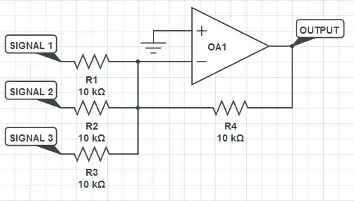
This circuit provides an output signal voltage according to the following equation: $$V_{out} = -R_4(\frac{V_1}{R_1} + \frac{V_2}{R_2} + \frac{V_3}{R_3}+ ...) = -(V_1 + V_2 + V_3)$$ The equation simplifies nicely in this case since all of the resistor values are equal, but you can easily change the values to set fixed gains for the channels. Additionally you can add quite a few more resistors for extra channels as needed (although its best to disconnect unused resistors/channels as they contribute noise to the circuit).

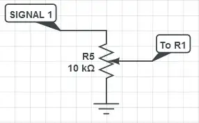
You can also take this configuration one step further and add individual gain control for each of your channels, simply by adding a potentiometer before the resistor on the given channel, as shown below. Since you are only dealing with mono channels, you would only need one potentiometer per channel (and only one op amp).

Channel Gain Control

As far as actual components go, the TL071 is a single op amp available in an 8-pin DIP package and can be run off of +/- 3.5V. DIP packages are usually much easier to work with than SMD parts if you're just starting out in electronics. Since your devices are pretty low fidelity, you won't have to worry about using a high-performance chip at all and could get away with a less expensive chip.

For extra information on audio mixing, you can check out this link, and more information on specific audio op amps can be found here

pipe
  • 14,271
  • 5
  • 44
  • 75
Luc
  • 553
  • 3
  • 10
  • See the last circuit you have with the potentiometer? Are there any considerations for adding a balanced XLR or TRS mono signal as opposed to an unbalanced one? – Antero Duarte Oct 19 '21 at 22:52