The current transfer ratio (CTR) defines how much of the forward current in the LED is optically transferred to the BJT as its collector current.
From your description, I am assuming it's wired as follows:
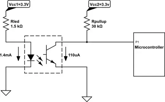
simulate this circuit – Schematic created using CircuitLab
So \$1.4\$mA in the LED \$\times 0.34 = 476\mu\$A of current in the collector, according to the CTR.
The current through the Rpullup caused by the voltage drop across the Rpullup will be:
$$ \mathrm{I} = {\mathrm{V} \over \mathrm{R}} = {3.3 \over 30000} = {110\mu\mathrm{A}} $$
so \$110\mu\$A will flow through Rpullup and the remaining \$476 - 110 = 366 \mu\$A would (under ideal conditions) be available to charge the P1 port of the microcontroller and sink it to logic 0. However, the rise time of the transistor is \$1.6\mu\$s and assuming a P1 gate capacitance of \$5\$pF worst case, and an internal \$10\$k pullup in parallel with the external \$30\$K pullup is \$7.5\$K, so the RC time constant is:
$$ 7500 \times 5\times 10^{-12} = 37.5\mathrm{ns}$$
This means that the gate capacitance will be charged up in just \$5\$ of those time constants, or \$187.5\$ns, well before the transistor is fully turned on and in saturation. After this, the transistor just continues to rise for the remaining rise time less the charging time, or
$$ 1.6\mu\mathrm{s} - 187.5\mathrm{ns} = 1.4125 \mu\mathrm{s}$$
at which point it just saturates at \$110\mu\$A
So this seems like enough current to pull down the micro's input port to logic LOW, but you need to look at your data sheet for the micro to determine what the actual input capacitance and pullups are.
When the optocoupler is switched off, the \$30\$K pullup will then be used in parallel with an internal pullup (I assumed \$10\$K internal) for \$7500\Omega\$ to charge the gate capacitor to the opposite logic level. Again, you will have \$110\mu\$A available (or even more if you include an internal pullup in parallel). So it seems like \$30\$K is fine here (because all the previously calculated time constants for logic LOW still apply here for switching to logic HIGH.)
You can easily avoid all these calculations if you use a reasonable current to begin with and middle of the road pullup like \$10\$K, at the expense of higher quiescent current draw. That optocoupler you are using can have \$60\$mA forward current in the LED, so give it \$5\$ to \$10\$mA, not \$1\$mA. \$1\$mA is also the minimum from the datasheet, and I like to stay away from minimums like that.