5

I've just started design in electronics and am a student of Electrical Engineering. The questions that I have are the following:

  1. How many resistors can be used for a voltage divider configuration? Is it just two or can there be more than that?

  2. When the voltage is divided can the voltage be further divided using other voltage divider configuration?

Ricardo
  • 6,164
  • 20
  • 53
  • 89
user38559
  • 87
  • 1

2 Answers2

4

You can make a voltage divider with any number of resistors, but you must remember that any current drawn from an output of a voltage divider must come through the resistors in that divider, so will affect the output voltage.

schematic

simulate this circuit – Schematic created using CircuitLab

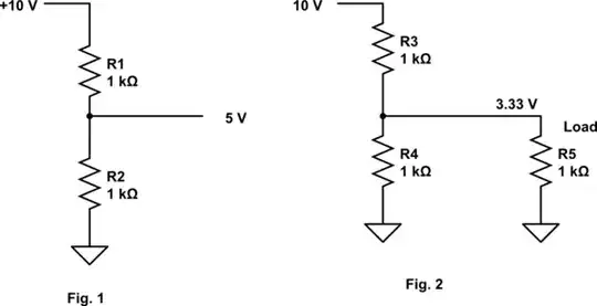
In Fig. 1, we have a simple voltage divider. Since the resistors are equal value, the output voltage will be half the input voltage (10V in gives 5V out).

However, in Fig 2 we've added a load (R5) intended to draw 5 mA from the voltage divider. However, that load is in parallel with R4, so we effectively have a 1K resistor (R3) in series with a 500 ohm resistor (R4 and R5 in parallel), so we only get 3.33 volts for our load, rather than the desired 5 volts.

When designing a voltage divider you must always make allowance for any currrent drawn from a tap on the divider, usually by ensuring that the current drawn by the load is much less than the current through the divider chain.

Peter Bennett
  • 59,212
  • 1
  • 49
  • 132
2

Yes, you can have more than two resistors in a voltage divider. And here is an example of that, which is called a voltage ladder:

Voltage ladder schematics

The purpose of such circuit is to allow the use of a single Analog to Digital Converter (ADC) pin (in an MCU, for example) to read the state of several buttons. The circuit does that by presenting the ADC pin AD0 with voltages between 0V and something just below VCC, depending on the pressed button. You get 0V when you press RIGHT, something just below VCC when you press SELECT, and something in between when the other buttons are pressed.

When a button is pressed, you can consider it as a closed circuit, and can disregard the resistors below it, as they are shorted to ground by the pressed button. So, each button press result in a diferente voltage divider configuration, with a different number of resistors acting in it.

See this other answer of mine for more information, such as how to determine the resistences of each resistor in the ladder.

Ricardo
  • 6,164
  • 20
  • 53
  • 89