I have an SN74HC595N shift register that I want to have output 5V on the Q outputs. If I power it with 5V on VCC, can I tie the SER, SRCLK, etc. pins directly to the 3.3V digital outputs on my microcontroller? I wasn't sure if I needed a transistor between each microcontroller pin, or if the lower voltage would be acceptable directly to the IC.
Asked
Active
Viewed 6,852 times
3 Answers
6
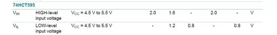
It is not guaranteed to work. You could use a level converter chip xx145, or you could use a 74HCT595, which will accept valid TTL levels at the inputs (and a 3.3V CMOS chip will give you that).
Edit: The margins are fine for 3.3V input, as alexan_e mentioned. See below.
Note that you should not connect any outputs form the HC595 or HCT595 directly to the 3.3V circuit.
A simple single-transistor level shifter was discussed here:
If you use a MOSFET you don't need the base resistor, so it can be even simpler.
addmoss
- 105
- 3
Spehro Pefhany
- 397,265
- 22
- 337
- 893
-
You mention the 0.5v and 3.15v levels in a way that seems to suggest that they refer to the 74HCT595 ("the chip I linked to"). This was probably not the intention so I think it would be better to clarify this by mentioning that these refer to 74HC595 and to add the 74HCT595 transition levels ( <0.8v for LOW and >2v for HIGH ) that will work fine with 3v3 signals. – alexan_e Mar 04 '14 at 18:56
-
Thanks for the answer - the HCT version seems like it would be the easiest way to accomplish this. On the other method, instead of a level converter, could I use a transistor with the collector tied to 5V, the emitter tied to the '595 pin, and the base connected to the 3.3V out from the MC? Thanks again. – user38201 Mar 04 '14 at 19:46
-
@alexan_e Thanks very much for catching that, I'll edit my answer appropriately. – Spehro Pefhany Mar 04 '14 at 19:48
-
@user38201 The HCT is the best and easiest way. I've edited the answer to include a reference to a single transistor level shifter. – Spehro Pefhany Mar 04 '14 at 19:55
-
Thanks - that link is helpful as well. I'll probably go with the HCT solution. – user38201 Mar 04 '14 at 20:04
2
I tested this last night to see what would happen. Here was the set up I used.
5 VDC from external power supply to bread board positive rail. Ground from same power supply to negative rail.
NodeMCU Dev board 2.0 powered via USB cable (HiLetgo brand).
- GPIO14 (Pin 5) (3.3 VDC) to SN75HC595 SER (PIN 14)
- GPIO0 (Pin 18) (3.3 VDC) to SN75HC595 ST_CP (PIN 12)
- GPIO2 (Pin 17) (3.3 VDC) to SN75HC595 SH_CP (PIN 11)
SN74HC595
- Connected to NodeMCU (Listed above)
- VCC (PIN 16) to 5 VDC power rail
- MR (PIN 10) to 5 VDC power rail
- OE (PIN 13) to Ground rail
- GRD (PIN 8) to Ground rail
- Q0 though Q7 to positive legs of LEDs (Resistors to ground.)
When pushing a simple loop (for int i = 0; i < 255; i++) the led output acted erratic. LEDs would light up out of order and with different results than what the micro-controller was instructing it to do.
I then started pushing the same value with a 100 ms delay. At first I was pushing the value 255 (b11111111). All the LEDs stayed on. I then switched to 0 (b00000000) with a 100 ms delay. Sometimes the lights would stay off, sometimes they would all come on, sometimes only a few would come on.
I'm not sure why the IC was reacting this way. When I removed the 5 VDC power supply from the breadboard and used 3.3 VDC the Shift register, LED outputs acted as expected. I got the proper results each time I latched the IC.
So the conclusion I came too was to use the same voltages for all inputs of the SN74HC595 shift register. If you need to up the voltage of Q0 - Q7 do so after via level shifting.
I hope this helped.
Westly White
- 121
- 1
0
You might be able to make this arrangement work just by adding pullup resistors from the '595 inputs to +5V. However, you can only add these pullups if your particular microcontroller has 5-volt-tolerant I/O pins. The \$V_{IH}\$ level for the '595 is too high for a 3.3V processor output, but adding pullup resistors may allow this to work for you. I wouldn't recommend this for a production design, however.
Edit: I was assuming that you really had the HC version of the '595. If you have the HCT version instead then please see the comment by @alexan_e instead.
Joe Hass
- 8,487
- 1
- 29
- 41
-
Thanks for the answer. My microcontroller is actually 5V tolerant, so I could do it this way. I guess it wouldn't be the best way though. – user38201 Mar 04 '14 at 19:42