simulate this circuit – Schematic created using CircuitLab
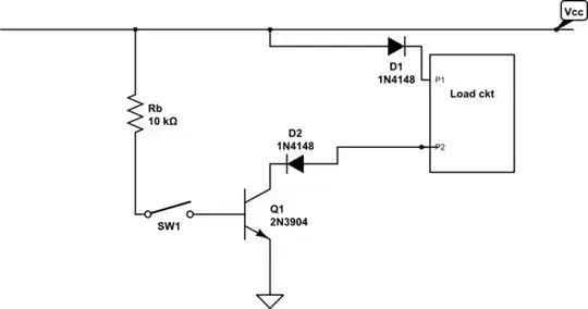
I was wondering whether I could use this circuit as a constant current source provided my load circuit impedance was less than Rb/hfe? All points of view are welcome....:)
simulate this circuit – Schematic created using CircuitLab
I was wondering whether I could use this circuit as a constant current source provided my load circuit impedance was less than Rb/hfe? All points of view are welcome....:)
It's not going to be an accurate constant current source because the voltage-current slope of the BJT is not that great but if you can live with this then that's OK: -
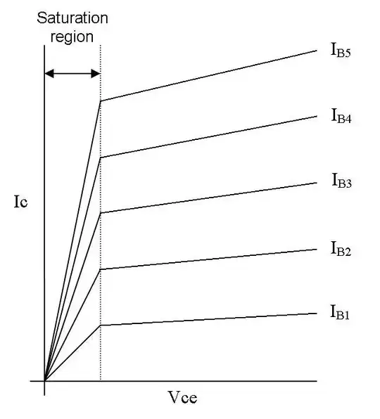
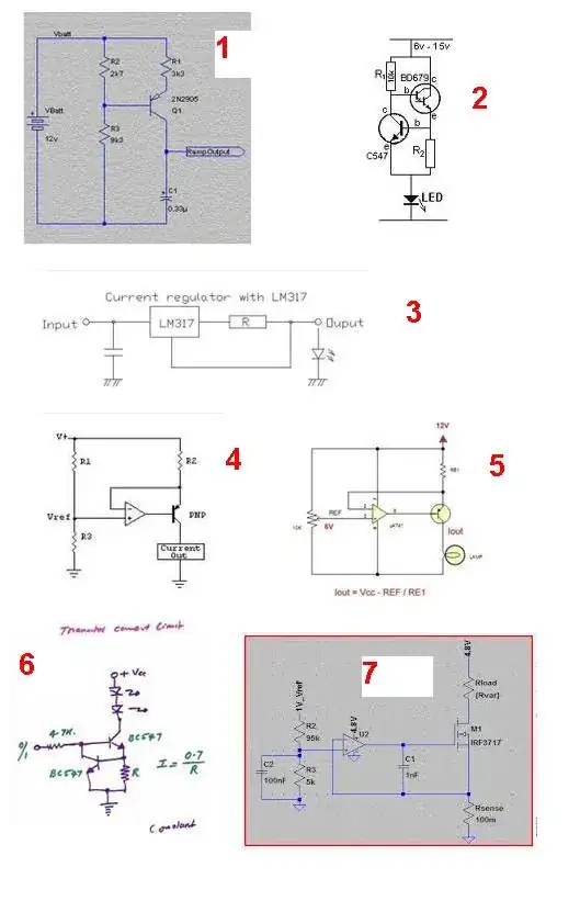
Ideally, once outside the saturation region, the lines would be horizontal to the base line of Vce - horizontal means that no-matter how you change the resistance of the load (which obviously changes the voltage across it and Vce, the current would remain the same. As you can see, the lines are not horizontal but have a gentle upward slope and get progressively less-horizontal for higher base currents. Added to this your circuit won't control the base current as neatly as you think - current through the emitter will slightly reduce the base current. If you want a better constant current source try one of these: -
A more common set up for a current source is as follows:
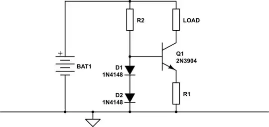
simulate this circuit – Schematic created using CircuitLab
This only works for currents in the mA range, otherwise these transistor and diodes will be overloaded.
No, you need to keep the base voltage constant. Try Figure 5 at http://en.wikipedia.org/wiki/Current_source, which uses an LED for this purpose.

You could switch right at the load, if you need to