Contents taken from Page 274 in the Mechanics of Materials: 6th Edition textbook. Authors: F.P BEER, E.R. JOHNSTON, J.T. DEWOLF AND D.F. MAZUREK ISBN:9780077565664.
Contents taken from Page 274 in the Mechanics of Materials: 6th Edition textbook. Authors: F.P BEER, E.R. JOHNSTON, J.T. DEWOLF AND D.F. MAZUREK ISBN:9780077565664
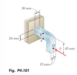
Knowing that the magnitude of the horizontal force P is 8 kN, determine the stress at (a) point A, (b) point B.
Honor Pledge: On my honor, I have neither given nor received unauthorized aid in doing this assignment.
R6.1 Solution
We must first analyze the cross sectional area.
Next calculate the moment of inertia of the rectangular cross section.
Next calculate the centroid of the rectangle
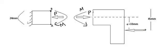
Next we show a free body diagram of the forces present on the bracket
Find the eccentricity
Calculate the bending couple using P = 8kN and e = 0.033m
Now we can calculate the stresses
Stress induced at point A:
Stress induced at point B:
R6.2: Problem 4.103
Contents taken from Page 274 in the Mechanics of Materials: 6th Edition textbook. Authors: F.P BEER, E.R. JOHNSTON, J.T. DEWOLF AND D.F. MAZUREK ISBN:9780077565664.
Contents taken from Page 274 in the Mechanics of Materials: 6th Edition textbook. Authors: F.P BEER, E.R. JOHNSTON, J.T. DEWOLF AND D.F. MAZUREK ISBN:9780077565664
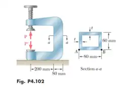
The vertical portion of the press of the press shown consists of a rectangular tube of wall thickness t = 8 mm. Knowing that the press has been tightened on wooden planks being glued together until P = 20 kN, determine the stress at (a) point A, (b) point B.
Honor Pledge: On my honor, I have neither given nor received unauthorized aid in doing this assignment.
R6.2 Solution
Given(s):
Rectangular cutout is 64 mm x 44 mm
Stress induced at point A:
Stress induced at point B:
R6.3: Problem 4.112
Contents taken from Page 276 in the Mechanics of Materials: 6th Edition textbook. Authors: F.P BEER, E.R. JOHNSTON, J.T. DEWOLF AND D.F. MAZUREK ISBN:9780077565664.
* Contents taken from Page 276 in the Mechanics of Materials: 6th Edition textbook. Authors: F.P BEER, E.R. JOHNSTON, J.T. DEWOLF AND D.F. MAZUREK ISBN:9780077565664. (*) = Reference to listed textbook
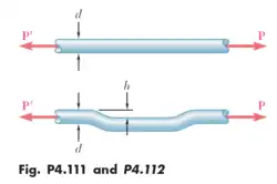
An offset h must be introduced into a metal tube of 0.75 in outer diameter and 0.08 in wall thickness. Knowing the maximum stress after the offset is introduced must not exceed 4 times the stress in the tube when it is straight, determine the largest offset that can be used.
Honor Pledge: On my honor, I have neither given nor received unauthorized aid in doing this assignment.
R6.3 Solution
GIVEN
Term
Desig
Value
Outer Diameter
Thickness
Inner Diameter
Area
Stress
The internal forces in the cross section are equivalent to a centric force P and a bending curve M. (*) Ex:4.07 on pg 272
EQ 4.49 on page 270(*) states:
(Where F = Force at centroid, P = Line of action load, M = Moment, and d = offset distance.)
EQ 4.5 on page 271(*) states:
(Distance from centroid)
The Moment of Inertia of a Hollowed Cylindrical Cross-Section:
To ensure the the max stress does not exceed 4 times the stress in the tube and making an assumption that P = 1, we can derive the following solution:
R6.4: Problem 4.114
Contents taken from Page 276 in the Mechanics of Materials: 6th Edition textbook. Authors: F.P BEER, E.R. JOHNSTON, J.T. DEWOLF AND D.F. MAZUREK ISBN:9780077565664.
Contents taken from Page 276 in the Mechanics of Materials: 6th Edition textbook. Authors: F.P BEER, E.R. JOHNSTON, J.T. DEWOLF AND D.F. MAZUREK ISBN:9780077565664. (*) = Reference to listed textbook
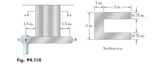
A vertical rod is attached at point A to the cast iron hanger shown. Knowing that the allowable stress in the hanger are and , determine the largest downward force and the largest upward force that can be exerted by the rod.
Honor Pledge: On my honor, I have neither given nor received unauthorized aid in doing this assignment.
R6.4 Solution
Max allowable stresses on the hanger:
Find centroid:
Take as a distance measured from left end of shape.
Due to same parameters,
Due to same parameters,
Must incorporate the parallel axis theorem to find moment of inertia:
b = base, h = height, A = area, and d = perpendicular distance between centroidal axis and parallel axis
Due to same parameters,
Total moment of inertia is:
The normal stress at point A is due to bending:
"The internal forces in the cross section are equivalent to a centric force P and a bending couple M " (Example Problem 4.07 page 272(*)):
distance of the force from the centroid of the cross section. (EQ 4.49 page 270 (*))
Normal stress due to centric load:
Combine:
(EQ4.50, p.221(*))
Total normal stress acting at point A.
Largest downward force:
Assuming conventions: = distance of acting force from the centroid
Largest upward force:
The limiting factor is at 7.86 kips force upward.
Apply negative sign throughout equation:
The Downward force becomes:
The Upward Force becomes:
Limit is at
R6.5: Problem 4.115
Contents taken from Page 276 in the Mechanics of Materials: 6th Edition textbook. Authors: F.P BEER, E.R. JOHNSTON, J.T. DEWOLF AND D.F. MAZUREK ISBN:9780077565664.
Contents taken from Page 276 in the Mechanics of Materials: 6th Edition textbook. Authors: F.P BEER, E.R. JOHNSTON, J.T. DEWOLF AND D.F. MAZUREK ISBN:9780077565664
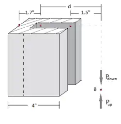
A vertical rod is attached at point B to the cast iron hanger shown. Knowing that the allowable stress in the hanger are and , determine the largest downward force and the largest upward force that can be exerted by the rod.
Honor Pledge: On my honor, I have neither given nor received unauthorized aid in doing this assignment.
R6.5 Solution
3D Representation of Figure 4.115
Max allowable stresses on the hanger:
Find centroid:
Take as a distance measured from left end of shape.
Due to same parameters,
Due to same parameters,
Must incorporate the parallel axis theorem to find moment of inertia:
b = base, h = height, A = area, and d = perpendicular distance between centroidal axis and parallel axis
Due to same parameters,
Total moment of inertia is:
The normal stress at point A is due to bending:
"The internal forces in the cross section are equivalent to a centric force P and a bending couple M " (Example Problem 4.07 page 272(*)):
distance of the force from the centroid of the cross section. (EQ 4.49 page 270 (*))
Normal stress due to centric load:
Combine:
(EQ4.50, p.221(*))
Total normal stress acting at point A.
Largest downward force:
Assuming conventions: = distance of acting force from the centroid
Largest upward force:
Apply negative sign throughout equation:
Egm3520.s13.Jeandona (discuss • contribs) 12:47, 10 April 2013 (UTC)