Introduction
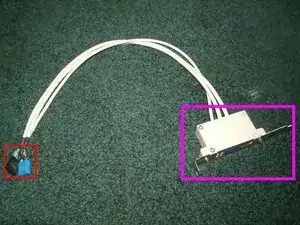
This is a teardown of a dual USB port bracket with LED activity lights for a desktop computer. These brackets, which mount on any open expansion card slot on a computer chassis, add two USB ports to the back of a computer using a connection to a 9-pin USB header on a motherboard. This one came out of a desktop with an MSI motherboard.
Tools
-
-
This part of the bracket consists of the circuit board enclosed in a plastic housing, which we will tear down in the next step.
-
These connectors plug into the USB headers on the motherboard.
-
-
-
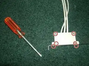
Use a Phillips #1 screwdriver to remove the four screws from the white casing and the two screws from the metal bracket.
-
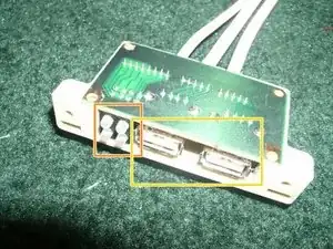
The two USB 2.0 ports.
-
The four LED lights, which light up depending on the activity of the USB ports.
-
-
-
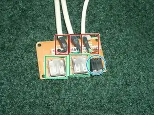
Raise the three connectors from the case and it's out!
-
The connectors highlighted in red lead to the wires that connect the bracket to the motherboard.
-
The two USB ports.
-
The LED activity lights.
-
2 comments
Why does it need its owe usb header just for the LED's.
That "usb header" is especially for MSI motherboard diag. status (mobo K8T Neo2 FIR 6802E, D-Bracket 2)