Introduction

  1. mcARAIDBpbJ1AWQF
    • Remove the case screws (red) and the keyboard screws (green).

    • Be sure not to lose these screws. You will need them to reassemble your laptop.

  2. cAa4UmaoGAch4SB1
    cAa4UmaoGAch4SB1
    4o2NUiP2eAYsDED4
    Or2ud1mSf22WslLQ
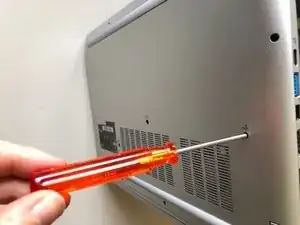
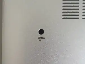
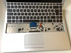
    • Using the hole provided under the case (see picture), push the keyboard out using a thin screwdriver or some other solid object.

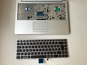
    • Hold onto the keyboard as you push the keyboard so as not to damage the two cables still attached.

  3. upHZZyNbKbsmWADI
    upHZZyNbKbsmWADI
    KcTcYcvdAXiFQtJ1
    yCvxHByYwFf1XuZj
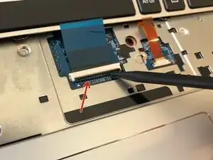
    • (Blue Cable) Push up on the thin black portion on the connector and gently pull out the blue ribbon cable until it comes out.

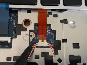
    • (Orange Cable) Remove the orange cable by sliding the gray part of the connector towards the screen, then gently pull on the ribbon cable.

  4. NZ4ENAlLJroIhYwL
    NZ4ENAlLJroIhYwL
    nfxEWWjoPRQPyJPR
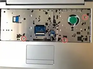
    • Unscrew the three screws that were under the keyboard. Be sure to hold onto these.

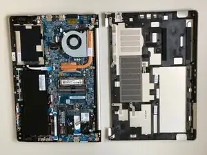
    • After these are removed, you can now remove the lower part of the case from the rest of the computer.

  5. YPHAgF2wWDcrQh2A
    YPHAgF2wWDcrQh2A
    sQuYcjL4BDpBwExl
    bpaOM2vYeckHGTF6
    • Remove the screw holding in the ssd.

    • Carefully remove the SSD from the connector.

  6. 2Jedh4yUea5VfAWp
    2Jedh4yUea5VfAWp
    imSORiqqmYtmlMch
    VMJ1YnCleIJBUgxP
    • Gently pull outwards on the clips to free the RAM stick.

    • Remove the RAM Stick from its slot.

  7. vJvhsDfTvQ62cA5q
    vJvhsDfTvQ62cA5q
    kK24gr56YTZQC6Mh
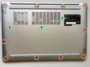
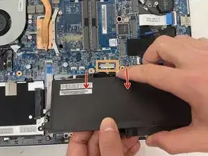
    • Remove the five Phillips screws securing the battery.

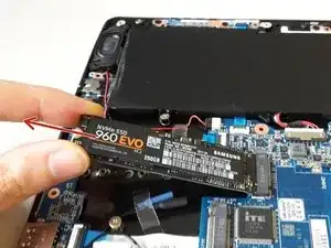
    • Unplug the power connector and lift the battery out in the direction of the arrows to remove it.

  8. RNkE2nh64PpsdIjy
    RNkE2nh64PpsdIjy
    irAZN5EpBo1qW6UV
    sJMteFFK5hkBgZ2E
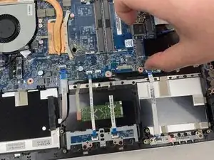
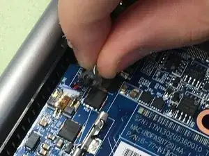
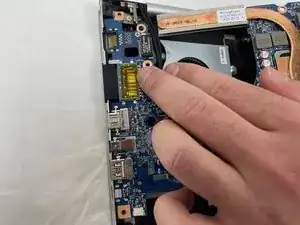
    • Lift the retaining latch and unplug the ZIF cable found under the keyboard.

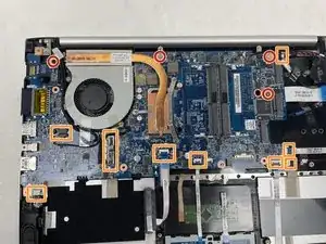
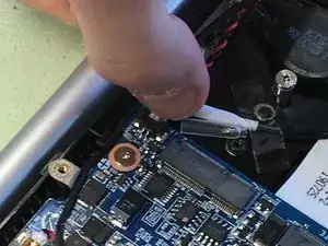
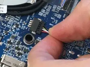
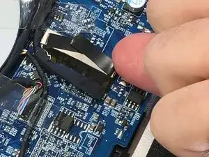
    • Disconnect the nine marked cables as detailed in the following steps.

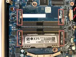
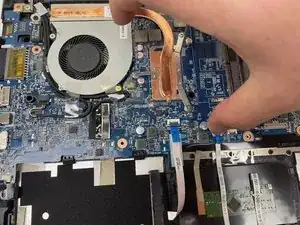
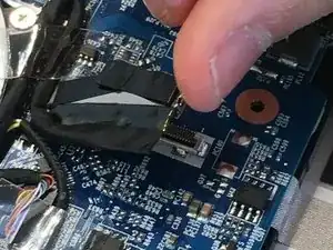
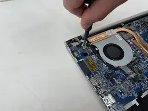
    • Remove the four screws securing the motherboard to the case.

  9. fk3TlkppfwtRUBvi
    fk3TlkppfwtRUBvi
    uGLi22kVYlLwJBWB
    gO5tYeZZ5E41nvDR
    • The cables with the blue reinforcing tabs are ZIF connectors that require you to lift the retaining lever before removing the cable.

  10. w6bSDwbAdJNvUXAx
    w6bSDwbAdJNvUXAx
    GRleSUiGWkU1RR6x
    e5rXWg4q24yjhEkI
    • Remove the SATA3 cable from the motherboard after disconnecting it.

  11. vNxCPPamErfgxAxQ
    vNxCPPamErfgxAxQ
    tIYxkkKlXvhAQBOH
    • Don't forget to remove these cables.

  12. XETHaFAPffurFgDT
    XETHaFAPffurFgDT
    EVysMXycwFKqEZD2
    • Note: The original instructions call for inserting your thumbnail firmly under the base of the display connector

    • However, the proper way to remove the display connector is to grasp the plastic strap on top of the connector and use it to pull the connector straight up.

  13. HQyQRirw5HFPJW1H
    HQyQRirw5HFPJW1H
    N4N3o6lXmSDmpemF
    iebeLVvBE32qT3X1
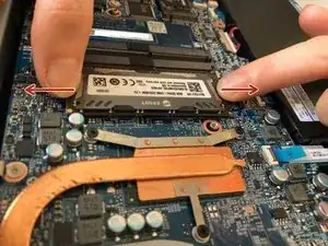
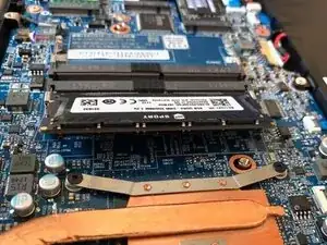
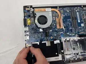
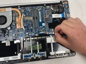
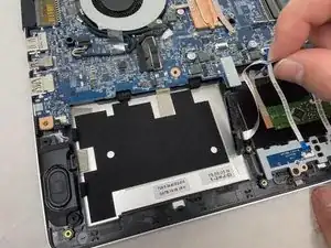
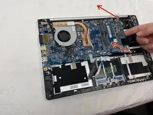
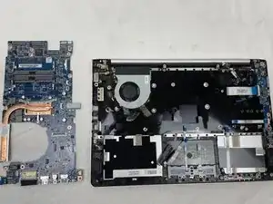
    • Once the screws have been removed, carefully lift the motherboard from the end indicated by the arrows.

    • Remember to disconnect the cables near the fan.

  14. XxManpeKamDxij2V
    • The motherboard has been successfully removed.

  15. p1uqqkrAOTDn2Hum
    p1uqqkrAOTDn2Hum
    mHpXURqgIaJd5I5D
    XgBgPJa1KS3rPYy1
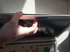
    • Unclip the display bezel from the frame starting at the top.

    • To remove the lower part, open the display as far as possible.

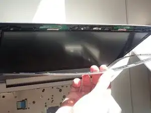
    • Warning, the frame of the screen may be glued at the bottom. When pulling as shown, there is a big risk of damaging the screen. You may want to use a plastic tab to separate it gradually.

    Attention ! le bas du cadre de l'ecran est collé (!!!) et lorsque l'on tire sur le cadre (depuis le haut, comme indiqué), l'écran se déchire...

    les indications fournies ici sont INCOMPLETES !

    Barth -

  16. lOEWyEg5MBZskMfj
    lOEWyEg5MBZskMfj
    B3YFvyT3XfGQPyZm
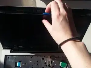
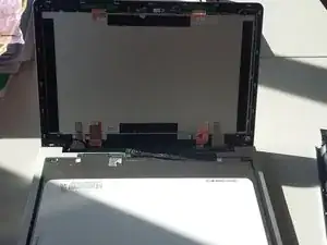
    • The LCD is secured with adhesive. Use an opening pick to separate the LCD from the display lid.

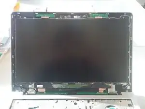
    • Carefully lay the LCD down on the keyboard.

    • Unplug the display connector at the bottom of the screen.

    Pour changer la nappe qui connecte l'écran à la carte mère, il manque des étapes. En effet; si vous souhaitez changer l'écran, vous pouvez garder la nappe qui est déjà en place. Mais si vous souhauitez changer la nappe elle même, il faut également la déconnecter de la carte mère, ET réussir à la passer dans la charnière à l'intérieur du capot... il manque des étapes.

    Barth -

Conclusion

To reassemble your device, follow these instructions in reverse order.

Felice Suglia

Member since: 15/06/13

33313 Reputation

5 comments

bonjour, pourriez-vous rajouter la manière dont on débranche le cable EDP entre carte mère et écran,

je n'ose pas tirer et je ne sais dans quelle direction! merci!

Didier Chakchouka -

Step 14 of the why! N131WU Motherboard Replacement guide shows how to unplug the other end of the display cable from the motherboard. You will need to follow the first four steps of that guide in order to gain access to it.

Jerry Wheeler -

merci! je vais regarder cela!

Didier Chakchouka -

Bonjour ,

Il n'est pas nécessaire de retirer la carte mère , seules les étapes 15 et 16 sont nécessaire pour changer l'écran

EkimiaMichel -

En effet, il n'est pas nécessaire de retirer la carte mère, mais il faut tout de même suivre l'étape 12 si on veut changer le câble EDP. Il n'est pas exclu que nous devrions mettre à jour certains de nos tutos.

Felice Suglia -