Introduction
-
-
Unplug any cables from your phone.
-
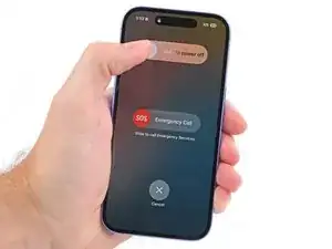
Hold the power and either volume buttons and slide to power off your phone.
-
-
-
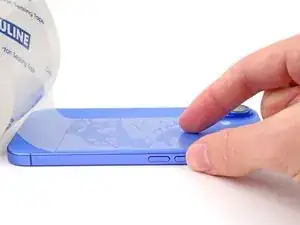
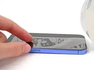
If your screen or back glass is badly cracked, lay overlapping strips of packing tape over the glass to protect yourself and make disassembly easier.
-
-
-
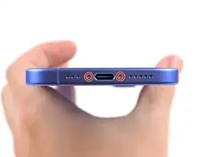
Use a P2 pentalobe driver to remove the two 7.7 mm-long screws on either side of the charging port.
-
-
-
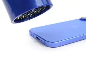
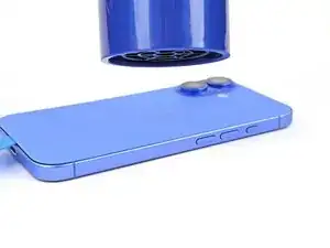
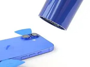
Use a hair dryer or heat gun to heat the bottom edge of the back glass until it's hot to the touch.
-
-
-
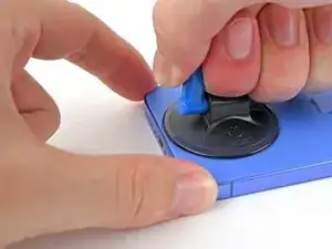
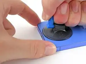
Apply a suction handle to the bottom edge of the back glass.
-
While supporting the frame with one hand, pull up on the handle with a strong, steady force to create a gap between the back glass and the frame.
-
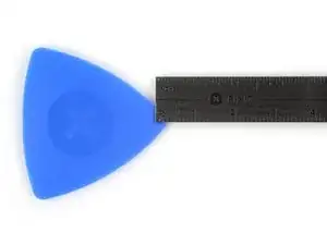
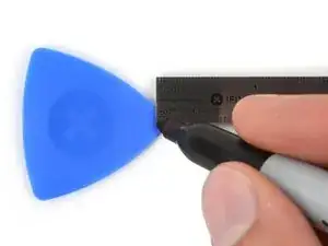
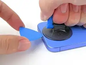
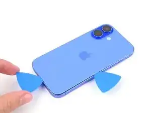
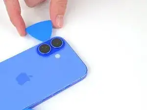
Insert the tip of an opening pick into the gap.
-
-
-
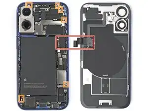
A delicate cable connecting the back glass to the phone, right next to the volume down button. Don't insert your pick here to avoid slicing the cable.
-
Multiple spring contacts around the perimeter of the phone.
-
-
-
Use a hair dryer or heat gun to heat the right edge of the back glass until it's hot to the touch.
-
-
-
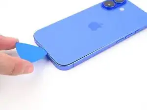
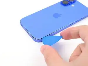
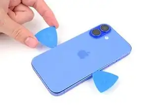
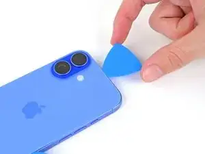
Slide your pick around the bottom right corner and to the volume down button to separate the adhesive and release the metal clip.
-
Leave this pick inserted to prevent the adhesive from resealing.
-
-
-
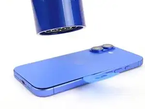
Use a hair dryer or heat gun to heat the left edge of the back glass until it's hot to the touch.
-
-
-
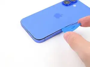
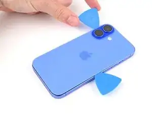
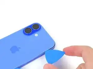
Insert a second opening pick at the bottom edge.
-
Slide the second pick around the bottom left corner and along the left edge of the screen to separate the adhesive and release the metal clips.
-
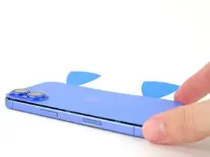
Leave this pick inserted at the top left corner to prevent the adhesive from resealing.
-
-
-
Use a hair dryer or heat gun to heat the top edge of the back glass until it's hot to the touch.
-
-
-
Slide your second opening pick around the top left corner and along the top edge to separate the adhesive and release the metal clips.
-
Continue sliding your pick around the top right corner until you reach the Action button.
-
Leave this pick inserted to prevent the adhesive from resealing.
-
-
-
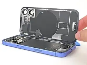
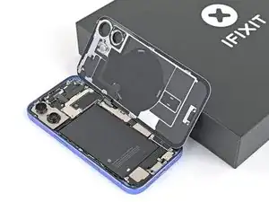
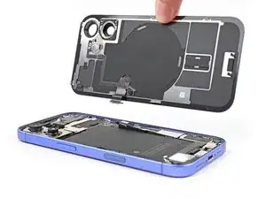
Swing open the back glass to the right of the phone to separate the remaining adhesive.
-
Support the back glass with a clean, sturdy object.
-
Remove the opening picks before continuing.
-
-
-
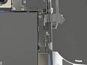
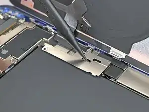
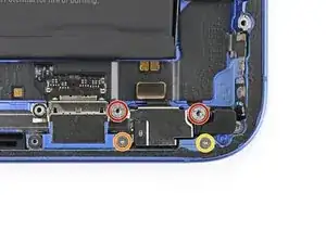
Use a tri-point Y000 driver to remove the two 1 mm‑long screws securing the middle connector cover.
-
-
-
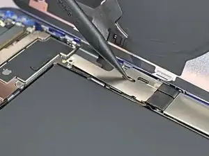
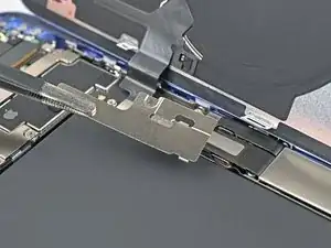
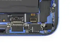
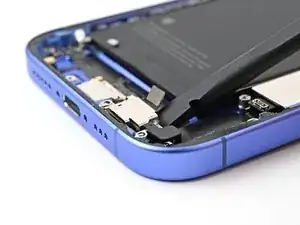
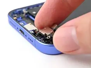
Insert the point of a spudger in either cutout on the middle connector cover.
-
Slide the cover towards the left edge of the phone and release its hook from its slot on the logic board.
-
Remove the cover.
-
-
-
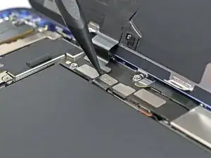
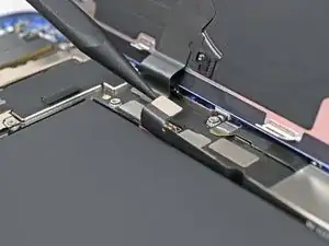
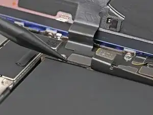
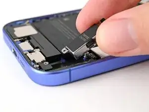
Use the point of a spudger to pry up and disconnect the wireless charging coil press connector.
-
-
-
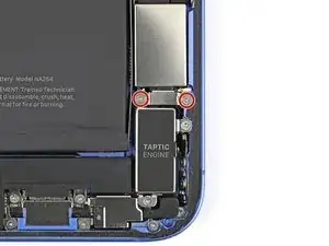
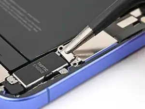
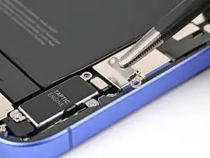
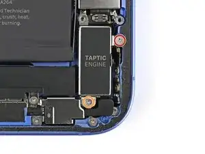
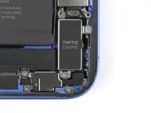
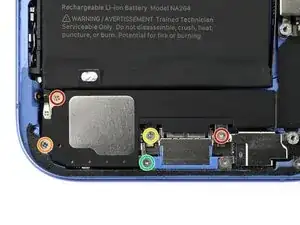
Use a Phillips screwdriver to remove the two 1.8 mm‑long screws securing the Taptic Engine bracket.
-
-
-
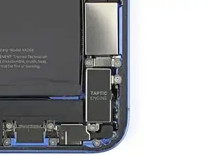
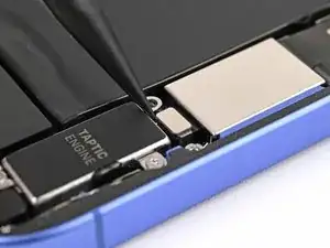
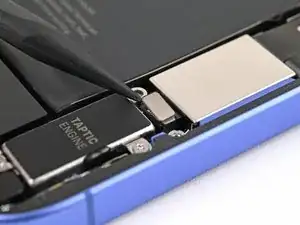
Use a Phillips screwdriver to remove the two screws securing the Taptic Engine:
-
One 2.2 mm‑long screw
-
One 1.7 mm‑long screw
-
-
-
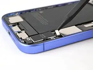
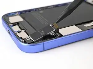
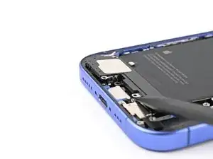
Use the point of a spudger to lift the Taptic Engine out of the frame.
-
Remove the Taptic Engine.
-
-
-
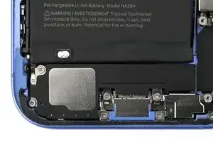
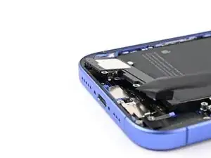
Remove the five screws securing the loudspeaker:
-
Two 1.5 mm‑long Phillips screws
-
One 2.0 mm‑long Phillips screw
-
One 2.9 mm‑long Phillips screw
-
One 1.2 mm‑long tri‑point Y000 screw
-
-
-
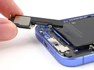
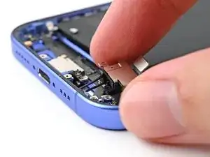
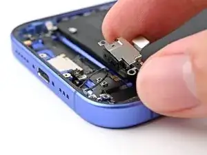
Use the point of a spudger to lift the loudspeaker out of the frame.
-
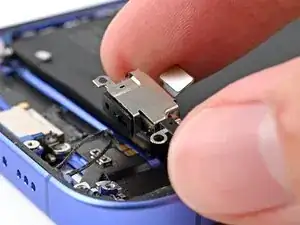
Remove the loudspeaker.
-
-
-
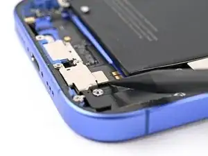
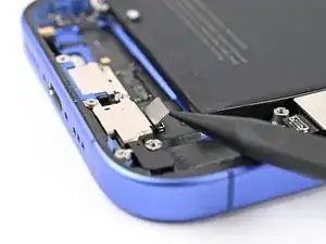
Remove the four screws securing the microphone:
-
Two 3.3 mm‑long standoff screws
-
One 1.1 mm‑long tri‑point Y000 screw
-
One 1.5 mm‑long Phillips screw
-