Introduction
Warning: The flash capacitors located under the front grip contain dangerous amounts of stored charge and will need to be safely discharged before removing the motherboard. Use a Capacitor Discharging Tool to do so.
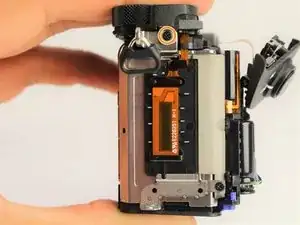
The motherboard is crucial for the function of both the software and hardware of the Sony a6500 camera; its failure will result in an inoperable device. If your camera is failing to turn on despite having a functional battery, the motherboard may need replacing. This guide will walk you through the replacement of the motherboard; it requires more steps than the other guides because it is embedded deep inside the camera. This guide will require opening tools, spudger, tweezers, JIS 0 screwdriver, JIS 00 screwdriver, and JIS 000 screwdriver.
-
-
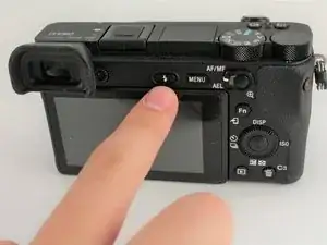
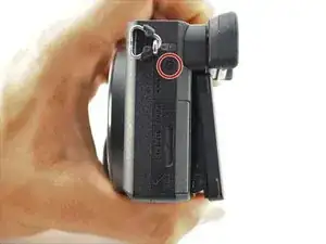
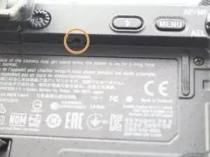
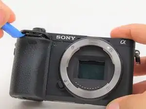
Press the flash popup button on the back of the camera.
-
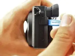
Remove one 5 mm JIS 00 screw from inside the flash compartment.
-
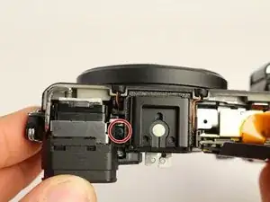
Remove one 4 mm JIS 00 screw.
-
-
-
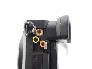
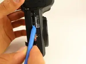
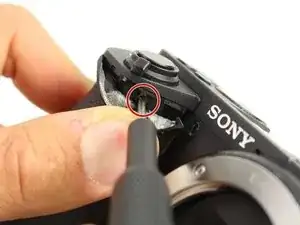
Remove the 2.5 mm JIS 00 screw from the side of the camera near the viewfinder.
-
Use the opening tool to pry off the small cover.
-
Remove two 2.5 mm JIS 00 screws from underneath the cover.
-
Remove a 5 mm JIS 00 screw from underneath the cover.
-
-
-
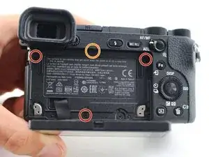
Remove three 2.5 mm JIS 0 screws from the back face of the camera.
-
Remove one 4 mm JIS 00 screw from the underside of the lip that overhangs the back of the camera.
-
-
-
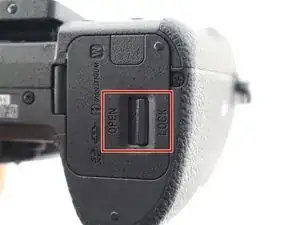
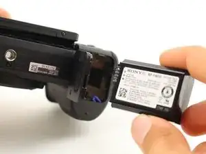
Flip the battery lock switch to open and open the battery compartment.
-
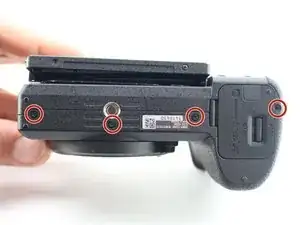
Remove three 2.5 mm JIS 00 screws from the top of the battery compartment.
-
-
-
Use the plastic opening tool to begin prying off the back of the camera from the side.
-
Continue to loosen the back until you can open it from the bottom.
-
-
-
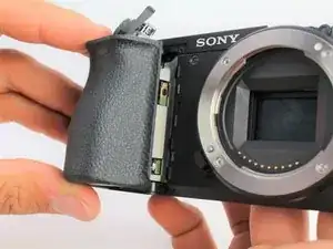
Use the plastic opening tool to peel down the rubber grip around the handle at least 1 cm.
-
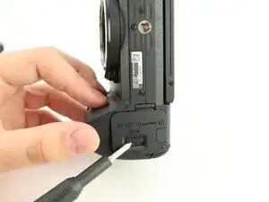
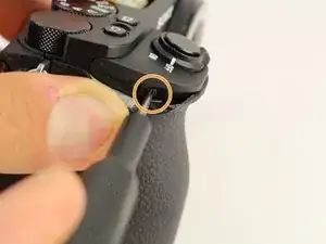
Remove one 3 mm JIS 000 screw from underneath the rubber grip on the right side.
-
Remove one 4 mm JIS 000 screw from the left side.
-
-
-
Insert a long, thin JIS 00 screwdriver through the two holes and into the battery compartment; remove the two 5mm JIS 00 screws inside it.
-
-
-
Use the long, thin, screwdriver to remove one 5 mm JIS 00 screw inside the camera accessible below the dials from the back.
-
-
-
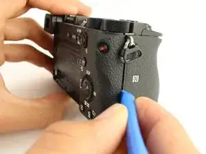
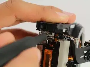
Use the plastic opening tool to gently lift up the shutter button assembly.
-
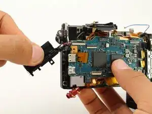
Grasp the front grip from the top and bottom and pull it off. It should come off easily with the shutter button out of the way.
-
-
-
Remove one 2.5 mm JIS 00 screw from where the shutter button assembly used to be.
-
Remove one 3 mm JIS 00 screw from the side of the camera.
-
-
-
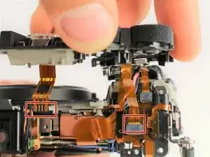
Carefully unplug the two ribbon connectors attaching the top assembly to the rest of the camera.
-
-
-
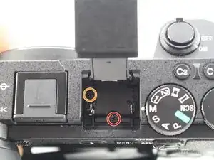
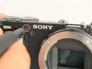
From the top of the camera remove one 4mm JIS 00 screw.
-
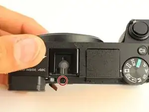
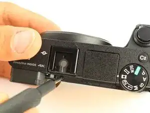
Remove one 5mm JIS 00 screw and the plastic bushing around it.
-
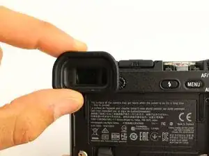
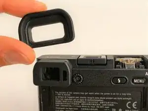
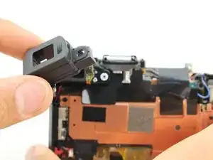
Remove the viewfinder's protective cover.
-
-
-
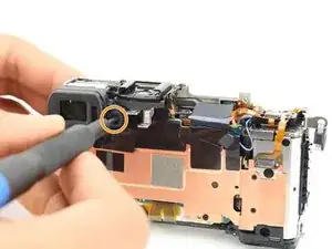
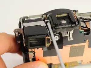
Use the spudger to pry the light sensor off the side of the viewfinder.
-
Remove one 2.5mm JIS 000 screw on the side of the viewfinder to release it.
-
-
-
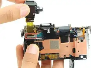
Lift the viewfinder out and flip up the tab to release the wire ribbon where it is connected to the motherboard.
-
-
-
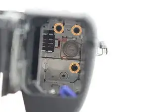
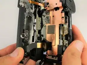
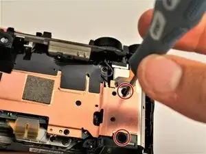
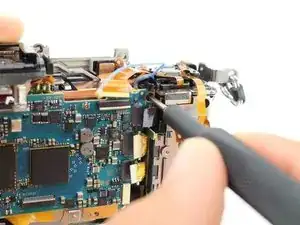
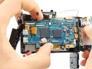
Remove two 2.5mm JIS 00 screws from the left side and bottom of the copper shielding.
-
Remove two 2mm JIS 000 screws from the right side of the copper shielding.
-
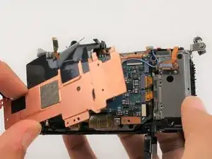
Pull the entire copper shielding piece off.
-
-
-
Remove one 4mm JIS 00 screw holding down a plastic spacer on the bottom left of the motherboard.
-
-
-
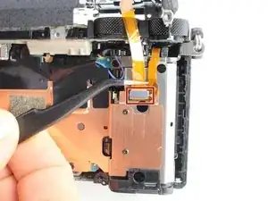
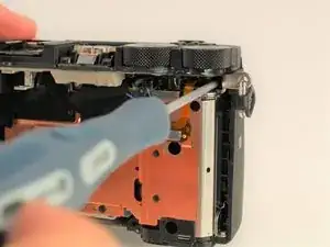
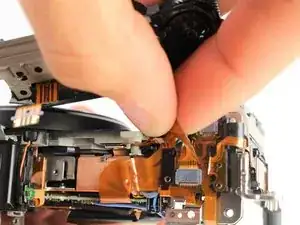
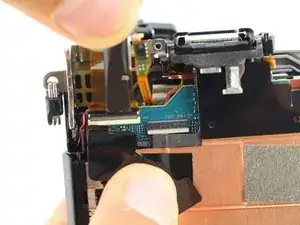
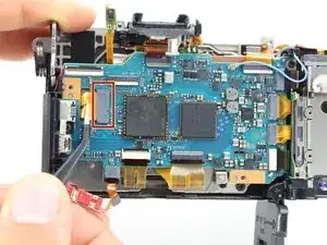
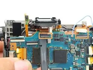
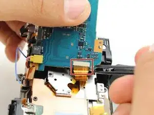
Carefully use tweezers to remove four wire ribbons on the right side of the motherboard.
-
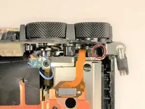
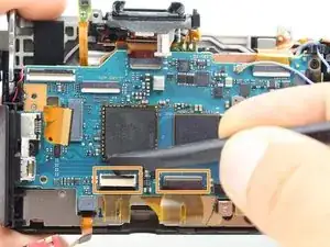
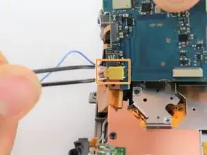
Remove the last two wire ribbons on the top of the motherboard by flipping up the locking tab and pulling them out.
-
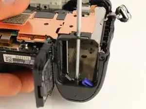
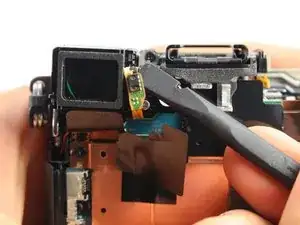
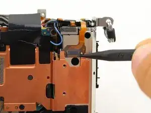
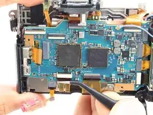
Pull the blue coaxial cable up off the board.
-
-
-
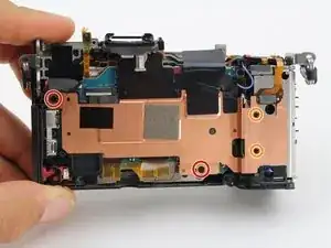
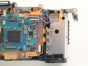
Remove one 4mm JIS 00 screw from the upper right of the motherboard and another from the far left.
-
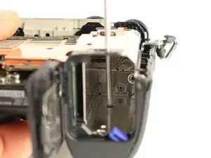
Remove the plastic housing for the power and HDMI ports.
-
-
-
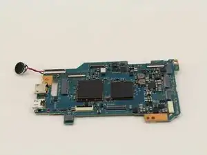
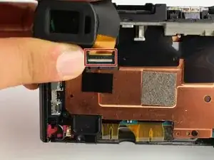
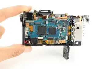
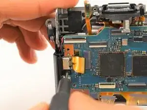
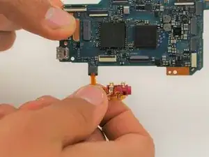
Grasp the motherboard from the sides and lift it up. It is still connected by two wires on the bottom right side.
-
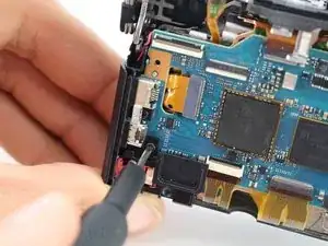
Pull the wire ribbon on the underside off with tweezers.
-
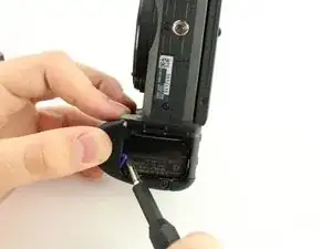
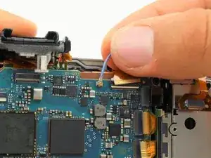
After you have discharged the capacitor, pull the yellow wire harness out using tweezers.
-


To reassemble your device, follow these instructions in reverse order.