Introduction
Use this guide to replace the USB-C port and charging board in your Samsung Galaxy S22+.
Before disassembling your device, completely discharge the battery. This reduces the risk of a dangerous thermal event if the battery is accidentally damaged during the repair. If your battery is swollen, take appropriate precautions.
Note: Retaining water resistance after the repair will depend on how well you reapply the adhesive, but your device will lose its IP (Ingress Protection) rating.
-
-
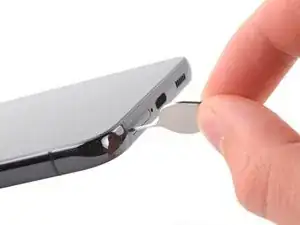
Insert a SIM eject tool, bit, or straightened paper clip into the SIM card tray hole on the bottom edge of the phone.
-
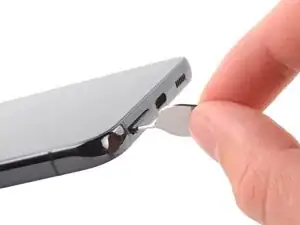
Press the SIM eject tool into the SIM card tray hole to eject the SIM card tray.
-
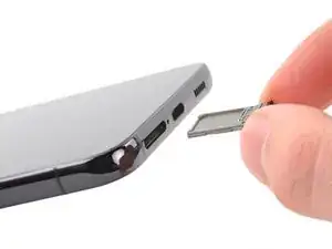
Remove the SIM card tray.
-
-
-
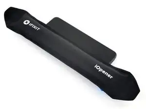
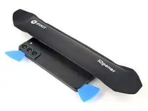
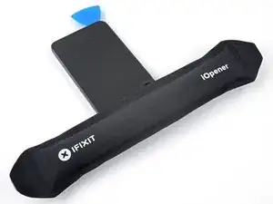
Prepare an iOpener and apply it to the bottom edge of the back cover for three minutes to loosen the adhesive underneath.
-
-
-
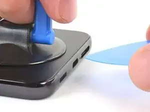
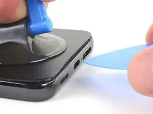
Secure a suction handle to the bottom edge of the back cover, as close to the edge as possible.
-
Lift the back cover with the suction handle to create a small gap between the back cover and the frame.
-
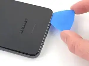
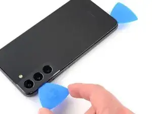
Insert an opening pick into the gap you created.
-
-
-
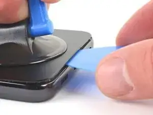
Remove the suction handle.
-
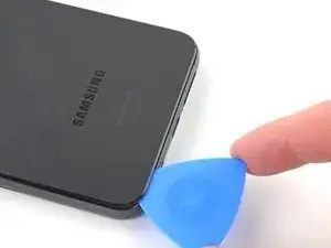
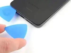
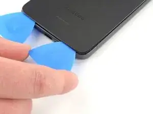
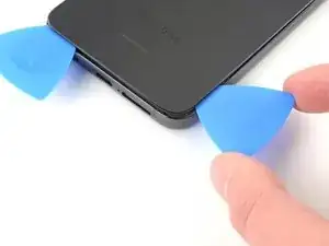
Slide the opening pick along the bottom edge to slice the adhesive.
-
Leave the opening pick inserted near the bottom left corner to prevent the adhesive from resealing.
-
-
-
Apply the heated iOpener to the left edge of the phone for 3 minutes to soften the adhesive.
-
Reheat your iOpener for 30 seconds if necessary.
-
-
-
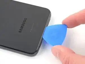
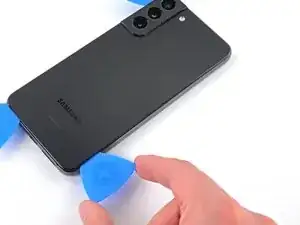
Insert a second opening pick into the gap created near the bottom left corner.
-
Slide the opening pick along the left edge to slice the adhesive.
-
Leave the opening pick inserted near the top left corner to prevent the adhesive from resealing.
-
-
-
Apply your heated iOpener to the right edge of the phone for 3 minutes to soften the adhesive.
-
Reheat your iOpener for 30 seconds if necessary.
-
-
-
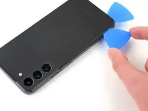
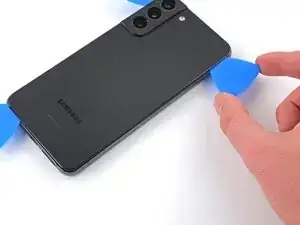
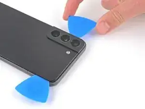
Insert a third opening pick into the gap created along the bottom edge.
-
Slide the opening pick around the bottom right corner of the back cover to slice the adhesive.
-
-
-
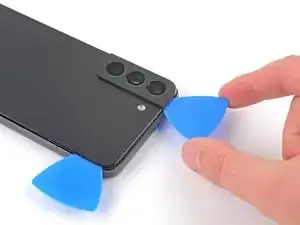
Continue sliding the opening pick up along the right edge of the back cover to slice the adhesive.
-
Leave the opening pick inserted near the top right corner to prevent the adhesive from resealing.
-
-
-
Apply your heated iOpener to the top edge of the phone for 3 minutes to soften the adhesive.
-
Reheat your iOpener for 30 seconds if necessary.
-
-
-
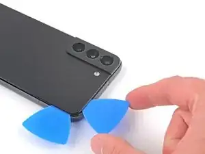
Slide the opening pick in the top left corner across the top edge to separate the remaining adhesive.
-
-
-
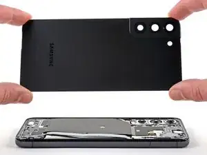
Remove the back cover.
-
This is a good point to power on your phone and test all functions before sealing it up. Be sure to power your phone back down completely before you continue working.
-
Remove any adhesive chunks with a pair of tweezers or your fingers. Apply heat if you're having trouble separating the adhesive.
-
If you're using custom-cut adhesives, follow this guide.
-
If you're using double-sided tape, follow this guide.
-
-
-
Use the pointed end of your spudger to pry up and disconnect the charging coil's press connector from the motherboard.
-
-
-
Use the pointed end of your spudger to pry up and disconnect the NFC antenna cable from the motherboard.
-
-
-
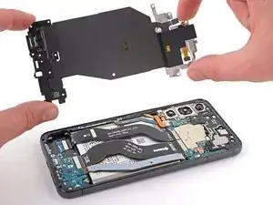
Insert your spudger in between the left edge of the loudspeaker and the frame.
-
Pry up to disconnect the clips securing the loudspeaker.
-
-
-
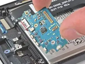
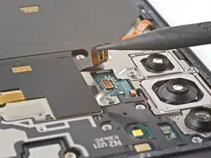
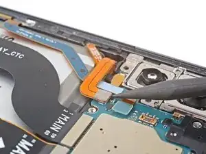
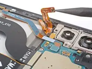
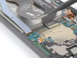
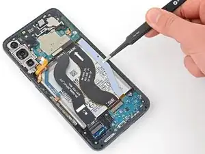
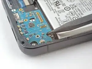
Use your spudger to pry up and disconnect the primary interconnect cable from the motherboard.
-
Use your spudger to pry up and disconnect the secondary interconnect cable from the motherboard.
-
-
-
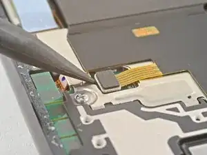
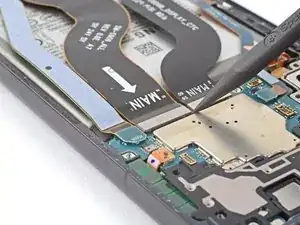
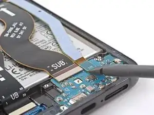
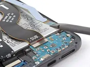
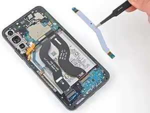
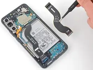
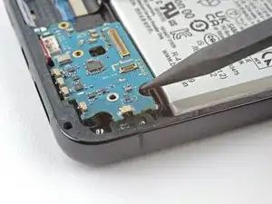
Use your spudger to pry up and disconnect the primary interconnect cable from the charging board.
-
Use your spudger to pry up and disconnect the secondary interconnect cable from the charging board.
-
-
-
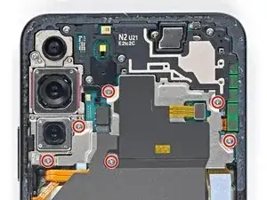
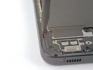
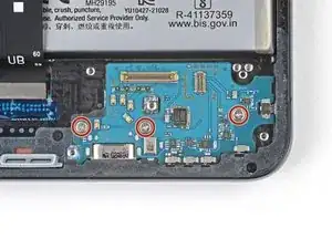
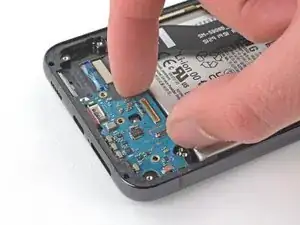
Use your Phillips screwdriver to remove the three 3.4 mm screws securing the charging board.
-
-
-
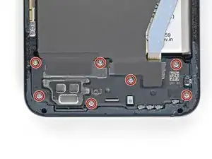
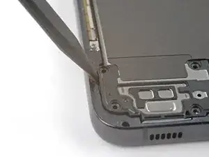
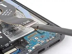
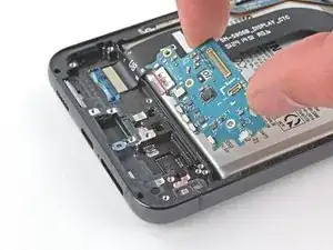
Insert the pointed end of a spudger between the top right edge of the charging board and the frame.
-
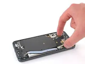
Pry up to lift the charging board enough to reach it with your fingers.
-


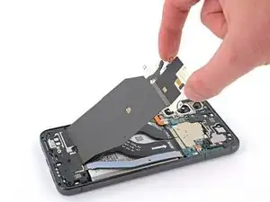

To reassemble your device, follow these instructions in reverse order.
Take your e-waste to an R2 or e-Stewards certified recycler.
Repair didn’t go as planned? Try some basic troubleshooting, or ask our Answers community for help.