
Introduction
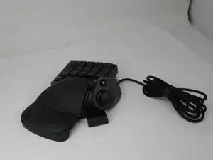
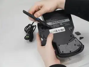
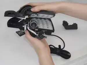
Sometimes the D-pad on the Razer Tartarus V2 model number RZ07-02270100-R3U1 can become stuck, hindering the device's performance. This guide will help you replace the D-pad on your device.
-
-
Gently peel off the rubber feet with a Jimmy.
-
Use a Phillips #0 screwdriver to remove the following screws:
-
Twelve 6.4 mm-long screws
-
Two 3.7 mm-long screws
-
-
-
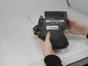
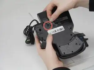
Peel up the bottom left corner of the largest sticker.
-
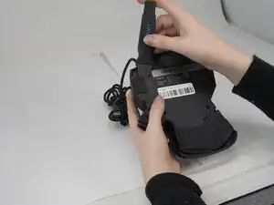
Remove the 6.4 mm-long Phillips #0 screw.
-
-
-
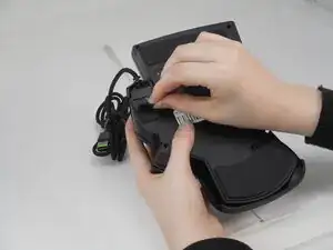
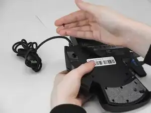
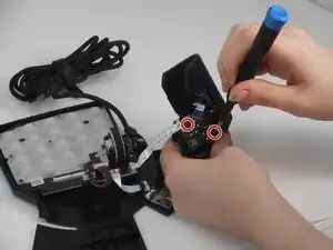
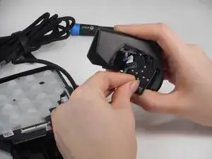
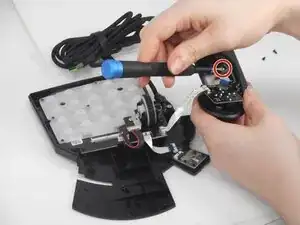
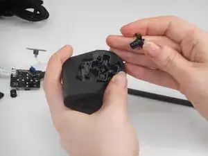
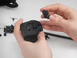
Carefully lift the joystick module up and out.
-
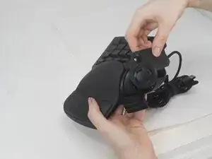
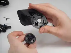
Separate the top and bottom casing of the keypad.
-
-
-
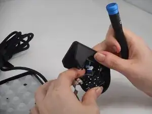
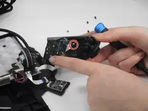
Remove the two 6.4 mm-long screws that secure the D-Pad PCB inside the casing with a Phillips #0 screwdriver.
-
There are two pairs of prongs that secure the D-Pad PCB to the housing. Use your fingernails to squeeze each set of prongs inward while gently prying the PCB away from the housing to disengage them.
-
Repeat the previous bullet for the remaining set of prongs.
-
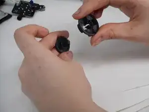
Carefully pull the PCB away from the housing.
-
-
-
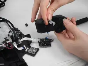
Remove the two 4.9 mm silver screws that secures the smaller PCB with a Phillips #0 screwdriver.
-
Gently pull the smaller PCB away from the white plastic underneath it.
-
-
-
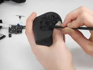
Use the hooked end of a halberd spudger to get under the edge of the smaller cross.
-
Pry all four arms of the smaller cross.
-
Remove both cross structures from the casing.
-
-
-
Pull the D-Pad out from its seated position. It will come off together with the D-Pad casing.
-


To reassemble your device, follow the above steps in reverse order.
Repair didn’t go as planned? Try some basic troubleshooting or ask our Answers community for help.