Introduction
Changing the top case will also give you a new trackpad.
Parts
-
-
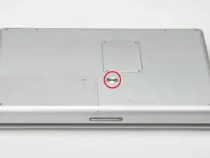
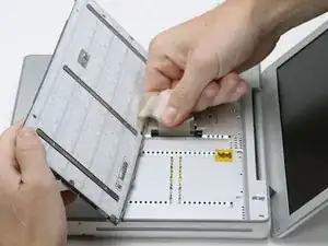
Use a coin to turn the battery locking screw 90 degrees to the right.
-
Lift the battery out of the computer.
-
-
-
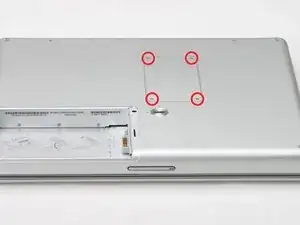
Remove the four Phillips screws from the memory door.
-
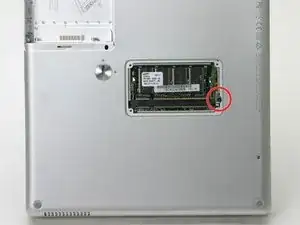
Slide the memory door away from the memory compartment.
-
-
-
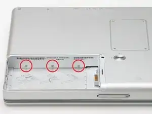
Remove the long black Phillips screw next to the memory card.
-
Remove the small EMI finger beneath the black screw.
-
-
-
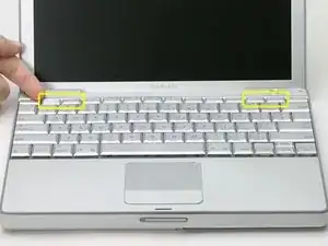
On the keyboard, remove the F1, F2, F11, and F12 keys.
-
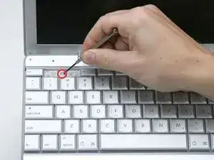
This is scary - take a deep breath before continuing. Place your index finger under the upper left corner of the key and lift up until you hear a click. Then, transfer your finger to the left edge of the key and lift up to pull the key off.
-
You're freeing the two tabs on the left of the key from the two small holes in the plastic scissors mechanism.
-
-
-
Use your fingernail or a small flathead screwdriver to peel up the gray stickers covering each of the screws.
-
-
-
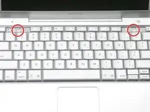
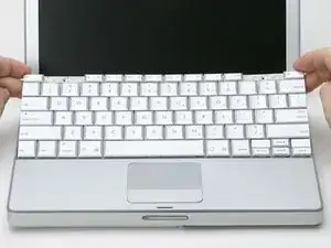
Lift the keyboard by the 'esc' and 'eject' keys and gently lift up until the keyboard is vertical.
-
-
-
Grasp the keyboard connector ribbon near the connector and disconnect it from the logic board.
-
-
-
Turn the computer 90 degrees clockwise and remove the two medium-length Phillips screws from the casing.
-
-
-
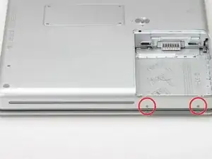
Turn the computer 90 degrees clockwise again, and remove only the bottom screw on either side of the hinge.
-
-
-
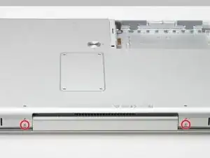
Turn the computer 90 degrees clockwise just one more time, and remove the two Phillips screws on the exterior wall of the battery compartment.
-
-
-
Turn the computer over and open it up.
-
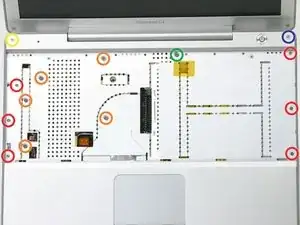
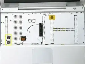
Remove the following 14 screws:
-
Six 2.5 mm Phillips on either side of the keyboard area.
-
Five 4.5 mm Phillips on the left half of the keyboard area.
-
One 7 mm hex in the upper left corner of the upper case (a T6 Torx driver will do the job nicely).
-
One 15 mm Phillips in the upper middle of the keyboard area.
-
One 16.5 mm hex in the upper right of the upper case (again, a T6 Torx driver will work well).
-
-
-
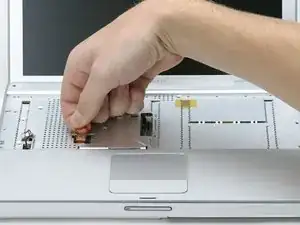
Peel up the two pieces of foil tape on the left side of the keyboard area.
-
Carefully disconnect the microphone and power cables from the logic board. Using your fingernails or a dental pick, carefully pry the connectors from their sockets. Make sure you're pulling only on the connector and not on the socket.
-
-
-
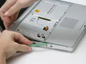
Starting at one of the upper corners near the screen, work around the frame, separating the upper case from the lower case.
-

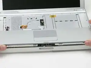
To reassemble your device, follow these instructions in reverse order.