Introduction
Use this guide to replace the charging port assembly in your Nokia G42 5G.
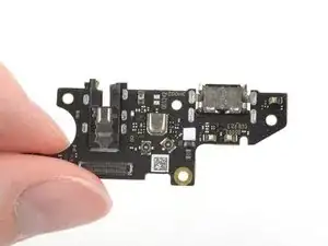
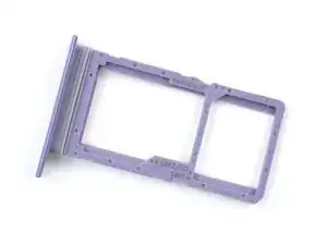
Note: The Nokia G42 5G's charging port assembly is a daughterboard that includes both the USB-C charging port and the headphone jack.
-
-
Power down your phone and unplug any cables.
-
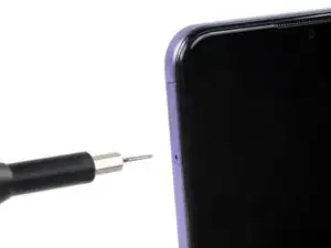
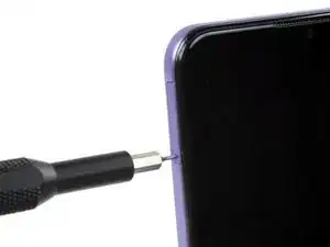
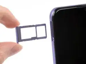
Insert a SIM eject tool, bit, or a straightened paper clip into the small hole on the SIM card tray on the upper left edge of the phone.
-
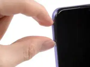
Press firmly to eject the tray.
-
-
-
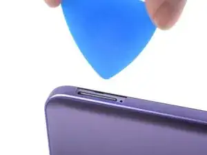
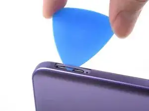
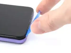
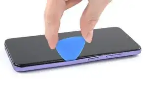
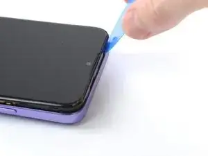
Position the opening pick at a steep downward angle between the back cover and the screen assembly.
-
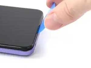
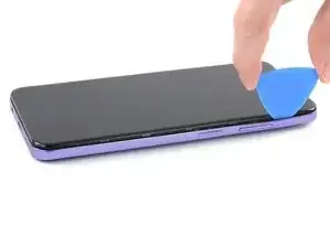
Slide the opening pick down the left edge of the phone to release the plastic clips.
-
-
-
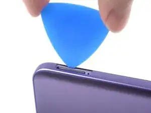
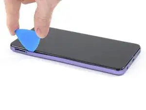
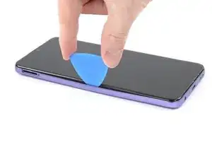
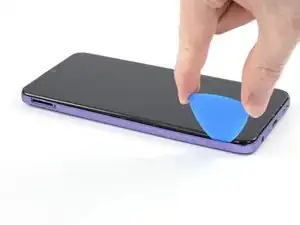
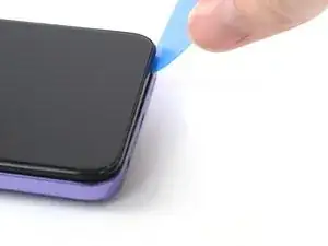
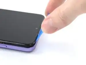
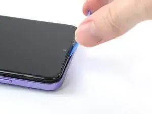
Turn the opening pick around the corner and continue to slide it along the bottom edge to release the plastic clips.
-
-
-
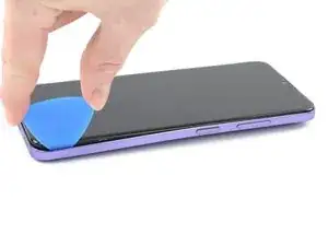
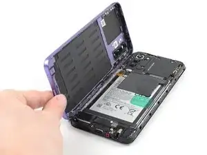
With the phone laying screen-side down, carefully lift the right edge of the back cover, opening it like a book.
-
Lay the back cover next to the phone.
-
-
-
Use a Phillips screwdriver to remove the 3.8 mm‑long screw securing the fingerprint reader bracket.
-
-
-
Use the pointed end of a spudger to disconnect the fingerprint reader by prying the connector straight up from its socket.
-
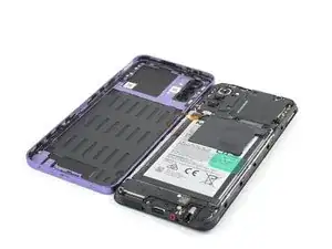
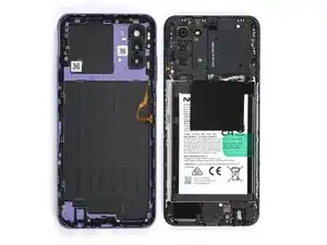
Remove the back cover.
-
-
-
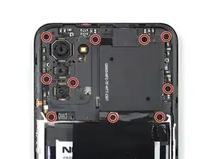
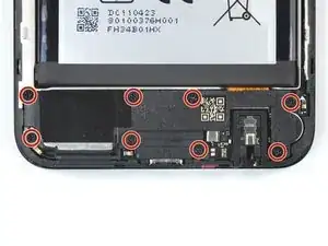
Use a Phillips screwdriver to remove the ten 3.8 mm-long screws securing the motherboard cover.
-
-
-
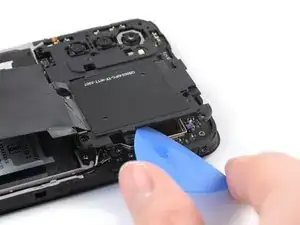
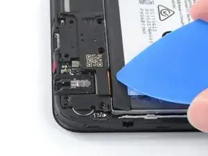
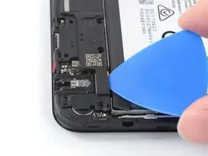
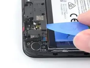
Insert an opening pick under the right edge of the motherboard cover.
-
Twist the opening pick to release the plastic clips.
-
-
-
Use the flat end of a spudger to disconnect the battery cable by prying the connector straight up from its socket.
-
-
-
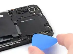
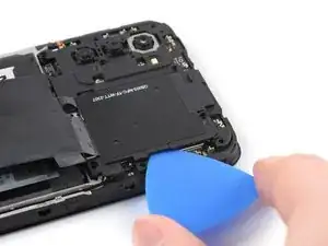
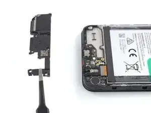
Insert an opening pick underneath the top right edge of the loudspeaker.
-
Twist the opening pick to release loudspeaker from the plastic clips holding it in place.
-
-
-
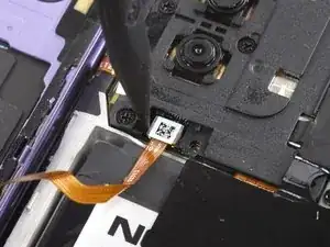
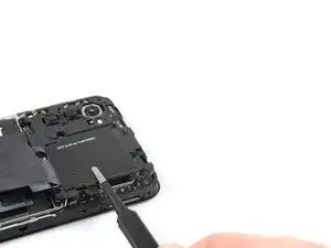
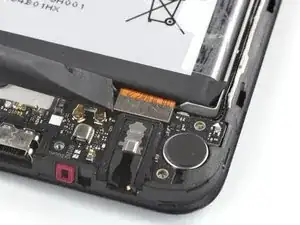
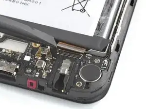
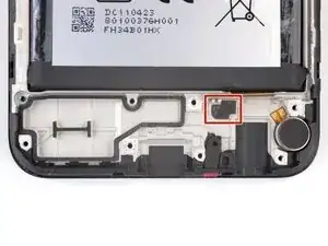
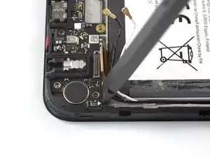
Use the flat end of a spudger to disconnect the interconnect cable by prying the connector straight up from its socket.
-
-
-
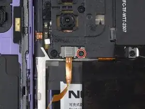
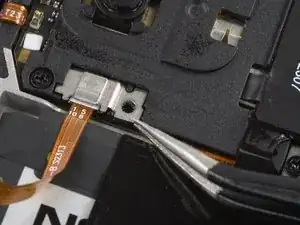
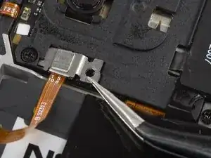
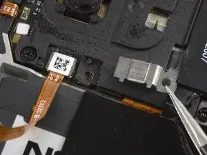
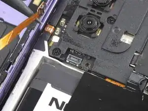
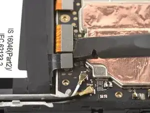
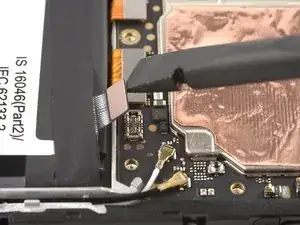
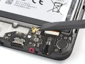
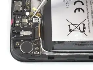
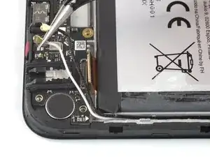
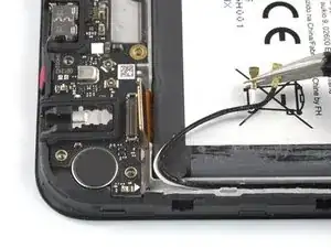
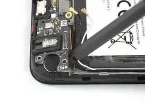
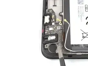
Use a spudger to disconnect the antenna cables by prying their coaxial connectors straight up from the sockets on the board.
-
-
-
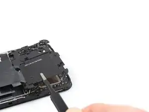
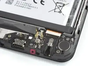
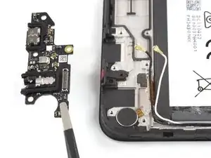
The top edge of the charging port assembly is held in place with adhesive.
-
Insert the flat end of a spudger underneath the top right edge of the charging port assembly.
-
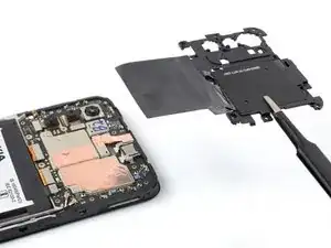
Pivot the charging port assembly up until you can grip it with your fingers.
-
-
-
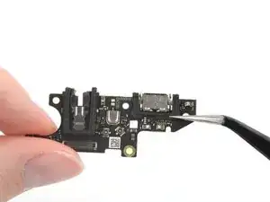
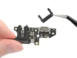
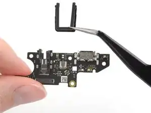
Use a pair of tweezers to remove the two black U-shaped rubber gaskets from the charging port and the headphone jack.
-
Only the charging port assembly remains.
-


To reassemble your device, follow these instructions in reverse order.
Take your e-waste to an R2 or e-Stewards certified recycler.
Repair didn’t go as planned? Try some basic troubleshooting, or ask our Answers community for help.

2 comments
Success!If I can do it anyone can. How ever if I never have to reconnect antennae cables and finger print readers again it will be too soon.
Badger -
Great! Took me a bit longer than expected (1h30) but I was delivered with sausages for fingers.