Introduction
-
-
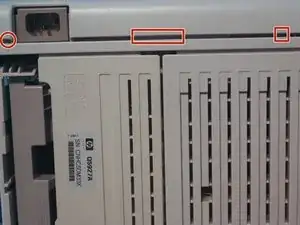
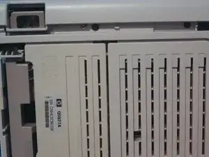
Pull on the two tabs on the back of the printer to release the left side cover.
-
Remove the cover by rotating it towards the front of the printer.
-
-
-
With the printer turned so that the right side is facing upwards, use a metal spudger to disengage 3 tabs holding the right side cover in place.
-
Lift the cover off of the printer.
-
-
-
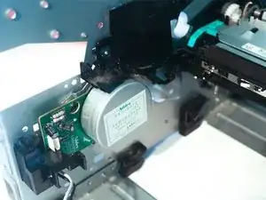
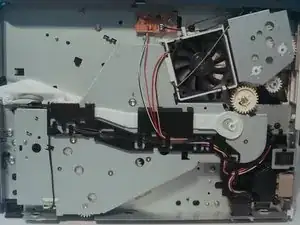
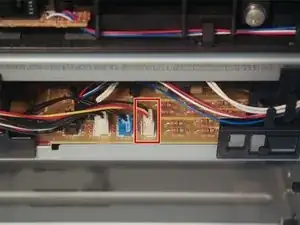
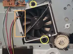
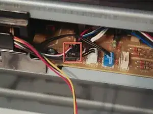
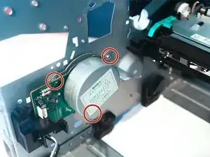
Disconnect the fan cable from the main board of the printer.
-
Remove the retaining clip holding the fan in.
-
Remove the 2 screws holding the fan in.
-
-
-
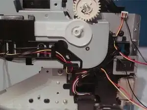
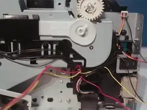
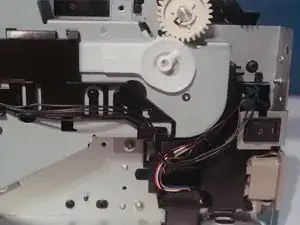
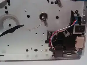
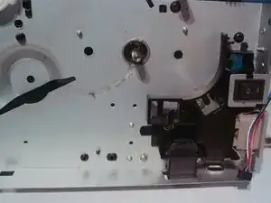
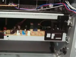
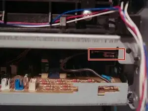
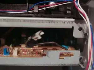
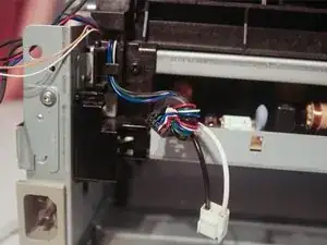
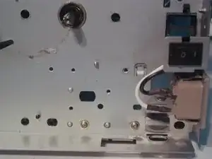
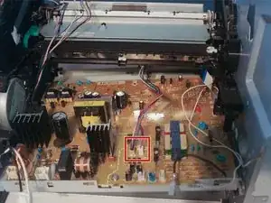
Disconnect one cable from the main board of the printer.
-
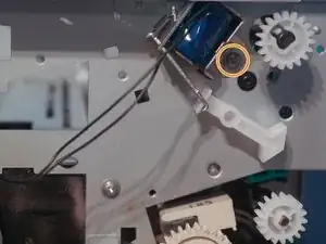
Disconnect the duplexer solenoid cable from the duplexer PCB.
-
Remove one screw on the duplexer PCB and remove the PCB from the printer.
-
-
-
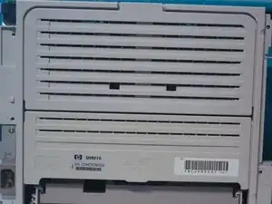
Pull on the two tabs on the back of the printer to release the left side cover.
-
Remove the cover by rotating it towards the front of the printer.
-
-
-
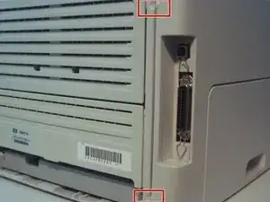
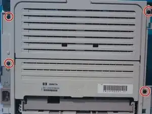
Remove 2 screws on the I/O port cover.
-
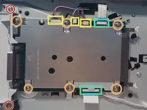
Remove 6 screws on the formatter.
-
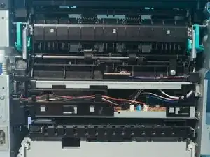
Disconnect 3 connectors from the formatter.
-
Disconnect 2 flat flexible cables from the formatter.
-
Remove the formatter from the printer.
-
-
-
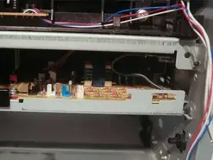
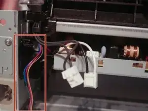
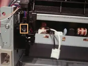
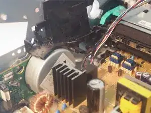
Remove the cable guide from the other side of the chassis.
-
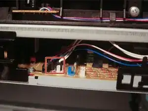
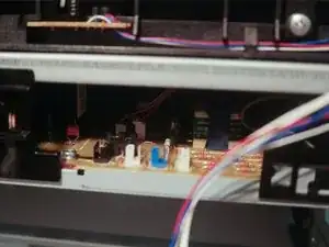
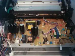
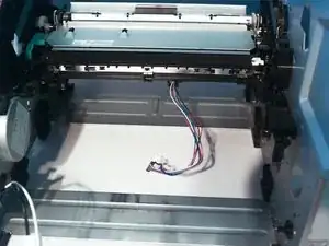
Disconnect 2 cables from the main board.
-
-
-
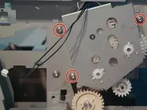
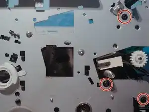
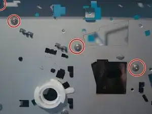
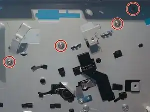
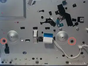
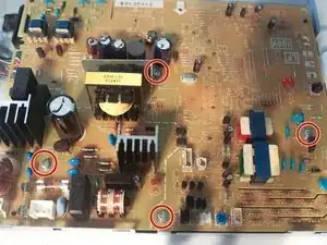
Remove 3 screws from the right side of the printer.
-
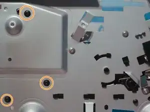
Remove 3 screws from the left side of the printer.
-
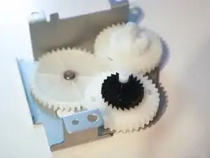
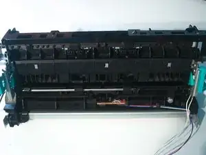
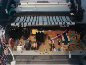
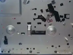
The fuser assembly can now be removed from the printer.
-
-
-
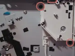
Remove 3 screws from the safety interlock assembly (one on top) and remove it from the printer.
-
-
-
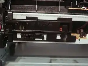
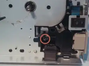
Remove one screw from the cable guide and remove the cable guide from the chassis.
-
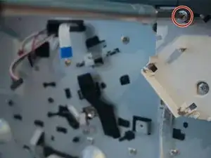
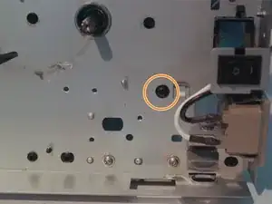
Remove one screw from the chassis.
-
-
-
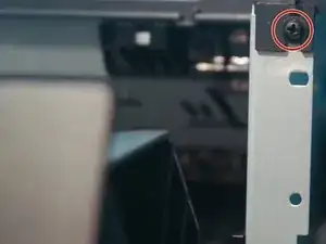
Remove 2 screws from the left side of the chassis.
-
Push the formatter and safety interlock cables through the hole in the chassis.
-
-
-
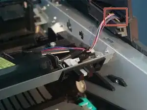
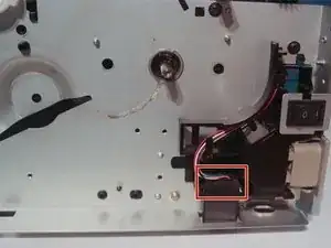
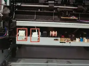
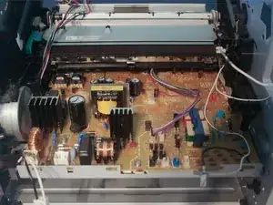
Bend the chassis to allow the control board to come loose, and disconnect the 2 cables from the paper feed assembly.
-
Remove the main board from the printer.
-


To reassemble your device, follow these instructions in reverse order.

One comment
hp 1320 printer not running