Introduction

eDP display cable removal prereq guide

  1. ENj2nRYJffBN2QaN
    ENj2nRYJffBN2QaN
    YjlDgdAsDVIlgqUJ
    GRNSY6XxqDVbUVQJ
    • Before you begin repairs, unplug your laptop and shut it down from the operating system. This ensures that the laptop isn't in standby/suspend mode.

    • The indicator LEDs along the edges should be unlit. The laptop should be silent.

    • If you accidentally turn on the laptop during repair, hold the power button down for 10 seconds to shut it down.

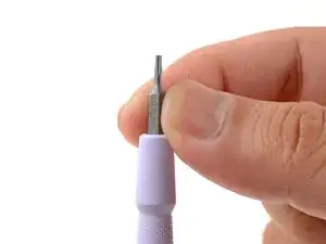
    • Make sure your Framework Screwdriver has the T5 Torx bit (labeled as T-5) facing outwards. If it's not, pull the bit out and flip it.

  2. U6Na255rCpfSIiOE
    • Set your Framework Laptop face-down on a clean work surface.

  3. kXDH52QdDLEsGWb3
    kXDH52QdDLEsGWb3
    xVySkCZQWfETEILq
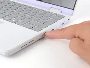
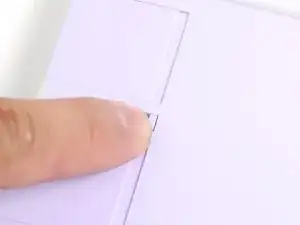
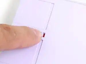
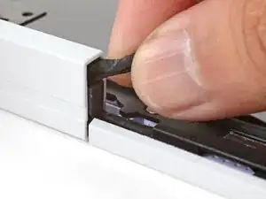
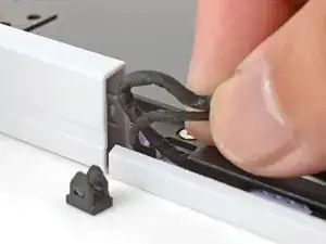
    • Use your fingers to flip the two Expansion Card latches (one for each side) into the unlocked position.

    • The latches display a red bar when they're unlocked.

  4. 3Ay6ujvbxLibrg3V
    3Ay6ujvbxLibrg3V
    3qShdMnt1UVHQQTE
    KJBBGAsADfIFXRuF
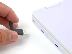
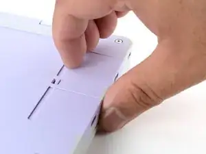
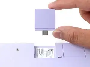
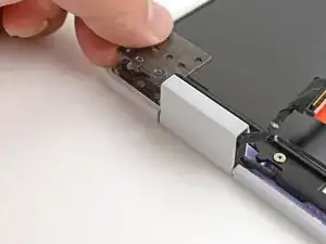
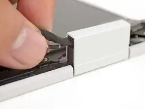
    • Grip the lip of an Expansion Card with your fingers.

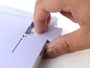
    • Pull the Expansion Card out of its slot and remove it.

    • If you have trouble pulling the Expansion Card out, you can also use the flat end of your Framework Screwdriver to push against the lip.

    • Repeat this procedure to remove all remaining Expansion Cards.

  5. mm1cOsKEjSReLdDl
    mm1cOsKEjSReLdDl
    nMf3oZliOaXESRbZ
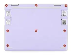
    • Use your Framework Screwdriver to fully loosen the eight captive T5 Torx screws on the bottom of your laptop.

    • Most screws in your Framework Laptop (including these) are captive—they're designed to stay in place after you loosen them.

    • Your laptop comes with a spare set of screws in the frame above the battery. Be careful—the replacement screws aren't captive.

  6. UomOMxHFjJlXOmVI
    • Flip your laptop face-up on your work surface.

  7. oXWu5f4x2x1bEW6V
    oXWu5f4x2x1bEW6V
    3moNOQ3UsMjPtUCn
    • Open the laptop lid so that both the screen and the base lie flat on your work surface.

  8. c6WsnKyZ5rguOoBJ
    c6WsnKyZ5rguOoBJ
    MZcsSlwlBdcXrEDK
    oihhCJTMXDodWRZU
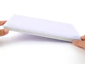
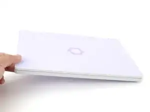
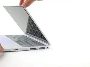
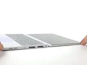
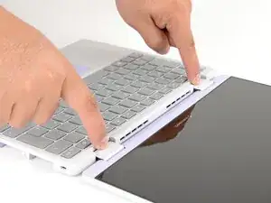
    • Use your fingers to grip the Input Cover in the hinge cutouts.

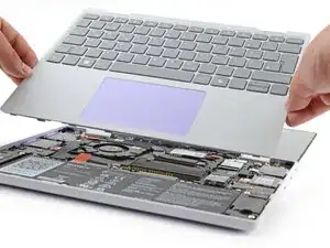
    • Lift upwards to swing the Input Cover up from the base of the laptop.

    • You may feel resistance from the magnets. If the cover feels like it's snagged, check that you've fully loosened the screws on the bottom of your laptop.

    • Remove the Input Cover.

  9. b5AQM3feYGn4ttQZ
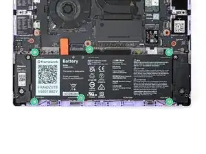
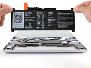
    • Use your Framework Screwdriver to loosen the six captive T5 Torx screws securing the battery.

  10. QMPLTpItI3EVDGEI
    QMPLTpItI3EVDGEI
    qXL3hfIHcHhpCpPg
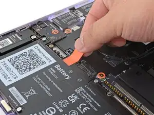
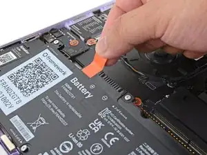
    • Grab the orange battery tab with your fingers and lift straight up to disconnect the battery.

    • The battery connector can be tight, requiring some force. If it feels like part of the battery won't come up, check that the battery screws are fully loosened.

  11. vBhTTUMPMdexvY2I
    vBhTTUMPMdexvY2I
    BpR3xLIgaPNfTJcs
    • Lift and remove the battery from the laptop.

  12. 1LspFmdiEPudL3Zr
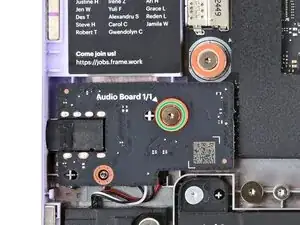
    • Use your Framework Screwdriver to loosen the captive T5 Torx screw securing the Audio Board along the left edge of the laptop.

  13. 6ipcMMTu1qUXBRPQ
    6ipcMMTu1qUXBRPQ
    bykbM2GttMpr464U
    tSWTJlYldWHuAX2M
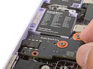
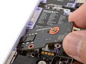
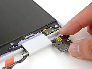
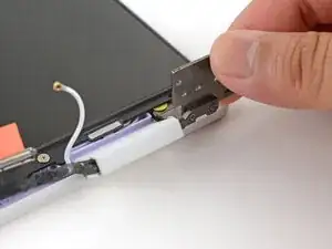
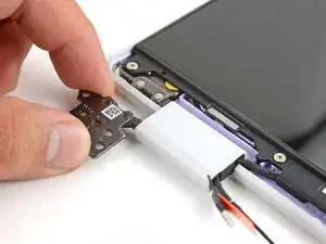
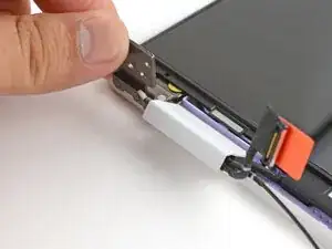
    • Use your fingers to lift the right edge of the Audio Board and pull it out of its recess.

    • Remove the Audio Board.

  14. LI6roagGYBQKm4KK
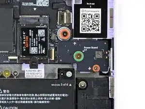
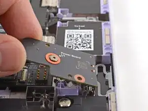
    • Use your Framework Screwdriver to loosen the captive T5 Torx screw securing the Power Button Board (labeled "Power Board").

  15. 1YWOCxYgWLZMlQme
    1YWOCxYgWLZMlQme
    HACIfBQ22OHPqWSW
    • Use your fingers to lift and remove the Power Button Board.

  16. WASDcqOnxB6NN21Z
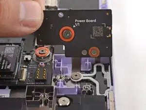
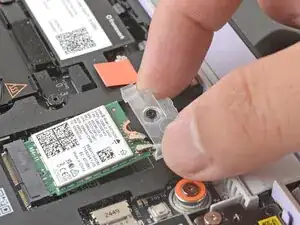
    • Use your Framework Screwdriver to loosen the captive T5 Torx screw securing the Wi-Fi card bracket.

    • The Wi-Fi card will pop up slightly when you unfasten the bracket.

  17. UVLUcXs34pQECrLM
    UVLUcXs34pQECrLM
    iiyH6iidQLvMvZiX
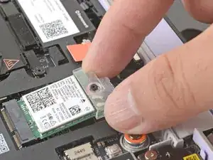
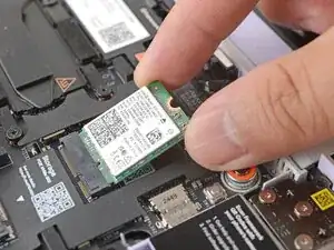
    • Grab the Wi-Fi card bracket with your fingers and slide it off the top of the Wi-Fi card.

    • Remove the bracket and store it in a safe location for reassembly.

  18. ki2LVyOtGbHyMXgX
    ki2LVyOtGbHyMXgX
    ryODAahNgYUHRZkG
    VNKH6uCVQXorSQJn
    • The Wi-Fi card has two delicate coaxial cable connectors. Follow this step carefully to avoid damaging them.

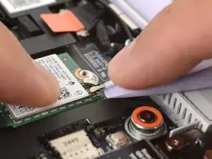
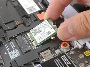
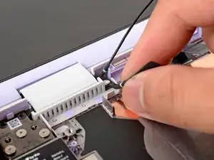
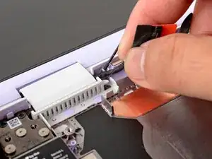
    • Press and hold the Wi-Fi card down with your finger.

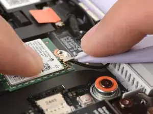
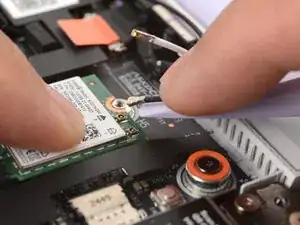
    • Slide the flat edge of your Framework Screwdriver under the white antenna cable, as close to the metal head as possible.

    • If you have angled tweezers, slide one arm of a pair of tweezers under the antenna connector, as close to the metal head as possible.

    • Gently lift the connector straight up to disconnect the white antenna cable.

    • Repeat the procedure with the black antenna cable.

  19. kfLYpLXD2YPL3bVh
    kfLYpLXD2YPL3bVh
    rufgfCYKRJZaZUey
    • Grab the Wi-Fi card by the edges and pull it out of its socket.

    • Remove the Wi-Fi card.

  20. pCPnjxGJThKdXVFW
    pCPnjxGJThKdXVFW
    VtUeEbfAPdISEWIY
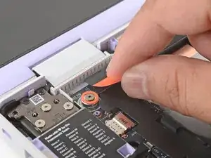
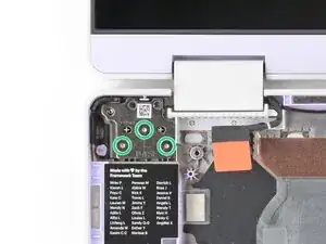
    • Use your fingers to grab the orange tab on the webcam cable, located near the left hinge.

    • Lift straight up to disconnect the cable.

  21. NGP43bwC1jJqWGKC
    NGP43bwC1jJqWGKC
    L2l1repCUHVC3LTg
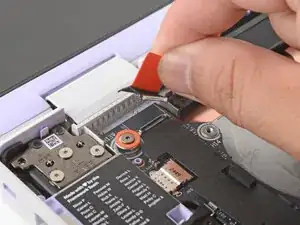
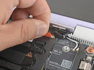
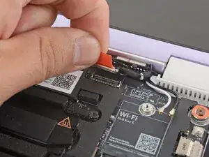
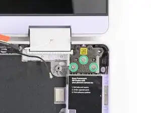
    • Use your fingers to grab the orange tab on the display cable, located near the right hinge.

    • Lift straight up to disconnect the cable.

  22. wCwXCyjSQUGA6gmJ
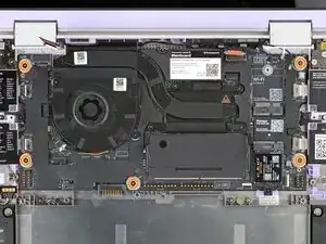
    • Use your Framework Screwdriver to loosen the five captive T5 Torx screws securing the Mainboard.

    • These screws are also physically marked with an orange ring on the Mainboard.

  23. apSPMCppisScbkwc
    apSPMCppisScbkwc
    Fp2JY2GcggxsJWJS
    • Make sure you've removed all Expansion Cards. Installed cards will hold the Mainboard in place.

    • Use your fingers to grab the Mainboard by its edges.

    • Lift and remove the Mainboard.

  24. BSvcRdLpsmIcKsmo
    BSvcRdLpsmIcKsmo
    22rw5AVWr2uhdgY5
    • Use your fingers to lift the black plastic loop securing the antenna cable, near the heat vents by the left hinge.

  25. 2n2oKLZuXXAcePPp
    2n2oKLZuXXAcePPp
    xhsj1Us6GrWLVDbD
    • Use your fingers to lift and guide the antenna cable out of the frame channel.

  26. cWlNG1Ci5cD5Mgye
    cWlNG1Ci5cD5Mgye
    FrI6DLf6RS3laSGL
    • Use your fingers to gently lift the webcam cable out of its plastic channel.

  27. sErSNNpqvuItEALJ
    sErSNNpqvuItEALJ
    dNFvlCgIOHMEw5Fw
    • Use your Framework Screwdriver to remove the six (three per hinge) 4.5 mm‑long T5 Torx screws securing the two hinges.

    • These screws are not captive. Store them in a safe location for reassembly.

  28. pdhexfmXmHku2ayx
    pdhexfmXmHku2ayx
    Q3QiG2nc2If5FNge
    duKZpb1SXJmyAlFX
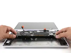
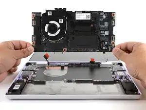
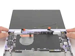
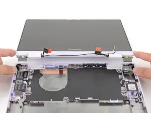
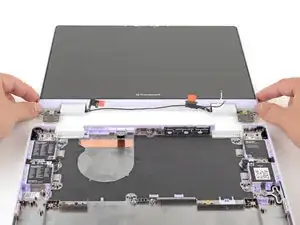
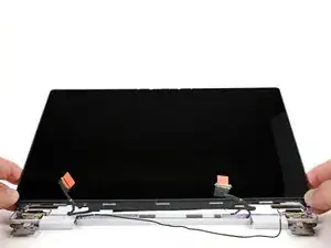
    • Use your fingers to lift the hinges over the Bottom Cover lip.

    • Separate the Top Cover from the Bottom Cover.

  29. nLAEKxJAXoTPCZDv
    nLAEKxJAXoTPCZDv
    2YdvFXYNKUMNpGBi
    • The Display Cover is held in place with magnets along its top edge and clips along its remaining edges.

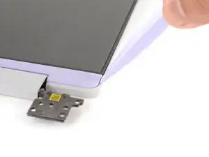
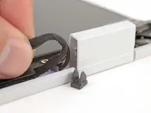
    • Use the flat end of your Framework Screwdriver to pry up the right edge of the Display Cover.

  30. iL1pI3MOcvS4vSQl
    iL1pI3MOcvS4vSQl
    ZMBhDh3p1WwJZJGM
    • Slide your fingers under the top edge of the Display Cover to release it from the laptop.

  31. dEOq6uPOZrppFeF5
    • Remove the Display Cover.

  32. 3XAr4SxtmboFKad5
    3XAr4SxtmboFKad5
    HcdHFSUqsWmOH4Xd
    yPAPZLyk3Wmc2Wfj
    • Use your fingers to twist the right hinge plate until it's flipped on top of the display.

    • The stiff hinge can be difficult to twist. Wear some work gloves, or use a cloth to help get a better grip.

  33. syHLCbrlyTARMW1Y
    syHLCbrlyTARMW1Y
    AicBveBXb2FRDgEi
    jfSJKfTpPQYqJwQv
    • Twist the left hinge plate until it's flipped on top of the display.

  34. 35eQgrZdVuNQypgQ
    35eQgrZdVuNQypgQ
    V6B5HpEoipZRTmRt
    • Use your fingers to grab the two cables coming out of the left hinge.

    • Pull gently to pop out the black cable clip and release the cables.

  35. uSNPqqXFB2Ae3brs
    uSNPqqXFB2Ae3brs
    6dEvbpPDjqAbHQ6G
    • Repeat the procedure on the right hinge to release the cables.

  36. X1E3fN6VdKOaXiaa
    X1E3fN6VdKOaXiaa
    ypxqouoFEdrj6Rnn
    gckONmYLVLIv1Vcv
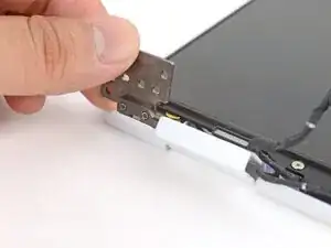
    • Use your fingers to twist both hinge plates back down so they lay flat on your work surface.

  37. SGUjRduXHcVyJoIa
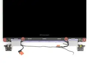
    • Use your Framework Screwdriver to remove the four 3.3 mm‑long T5 Torx screws securing the display to the Top Cover.

    • These screws are not captive. Store them in a safe location for reassembly.

  38. 1iVFacJPR6LWXyDW
    1iVFacJPR6LWXyDW
    MvevxLkPPkQJGYWM
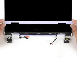
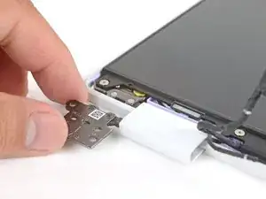
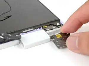
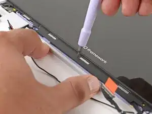
    • Use your fingers to hold the bottom edge of the Top Cover in place.

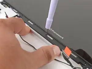
    • Insert the bit end of your Framework Screwdriver into the small hole on the display, below the Framework logo.

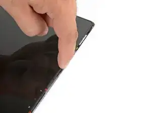
    • Slide the display down towards the hinge edge to release the tabs holding the top edge of the display in place.

  39. aU2UgiidOMei4F1V
    aU2UgiidOMei4F1V
    OPFSS6oTEMqLAbac
    • Use your fingers to lift the top edge of the display from the Top Cover.

  40. 6yarFKMvGlYqeXiw
    6yarFKMvGlYqeXiw
    BgQ3ivonUZnky4Sm
    • Lift and remove the display from the Top Cover.

  41. UUyeBtZOsVkNnFwG
    UUyeBtZOsVkNnFwG
    wZJm45UxRVWkMF3Z
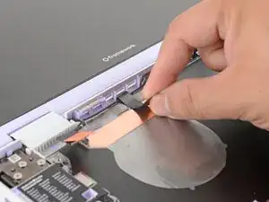
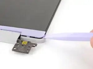
    • Slide the flat end of your Framework Screwdriver under the grounding tape securing the display cable.

    • Lift slowly to separate the tape from the display.

  42. sAbjOG5bYeL5XgAP
    sAbjOG5bYeL5XgAP
    SunterJMx3PNG5fP
    BeXmZI24lRsMhjS1
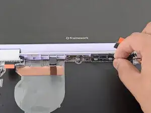
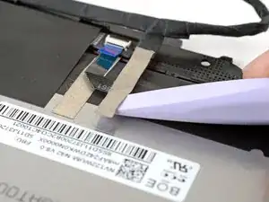
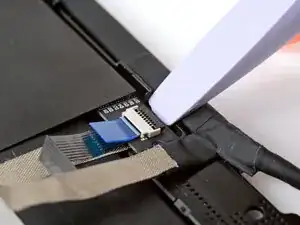
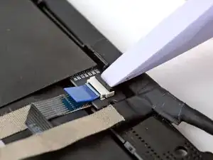
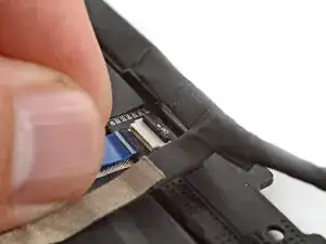
    • Use the flat end of your Framework Screwdriver or a fingernail to gently pry up the locking tab on the touch control ZIF connector near the hinge edge of the display.

    • Use your fingers to grab the touch control cable by the blue tab and slide the cable out of the connector.

  43. ZLFO4DQr6mKF246n
    ZLFO4DQr6mKF246n
    ZX6pDwKqRSZyWHYM
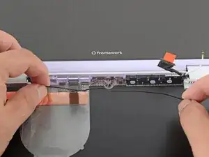
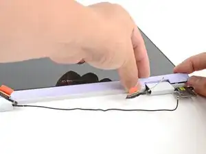
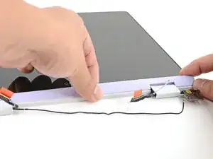
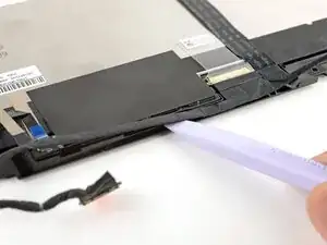
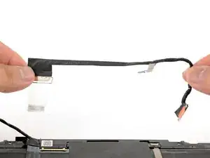
    • Slide the flat edge of your Framework Screwdriver under the length of the display cable to separate it from the display.

  44. VaOfDmmWuGgWDSHp
    VaOfDmmWuGgWDSHp
    TeaFZnC2NesByePe
    • Use your fingers to peel up the clear tab covering the display cable connector.

  45. LqBmCLOttgKwqSMl
    LqBmCLOttgKwqSMl
    mqcmkNCZEtEw25sG
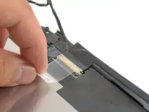
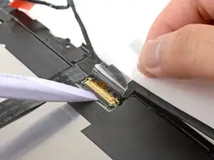
    • Use the flat end of your Framework Screwdriver to flip up the locking bar around the display connector.

  46. XQWuwpPWvZsrnMId
    XQWuwpPWvZsrnMId
    oayZEiusLZ4QAsKP
    • Make sure the locking bar doesn't fall back in place while you disconnect the display cable.

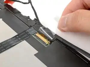
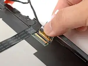
    • Grab the display cable near the connector and slide it out of the connector.

    • If you have trouble getting the cable to slide out, gently wiggle it to loosen the connection.

  47. CLdboO5DE22QEaB5
    • Remove the display cable.

Arthur Shi

Member since: 03/01/18

296850 Reputation

0 comments