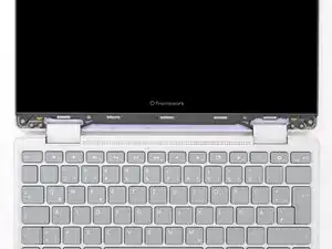
Introduction
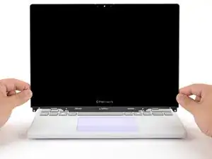
Display removal prereq guide
Tools
-
-
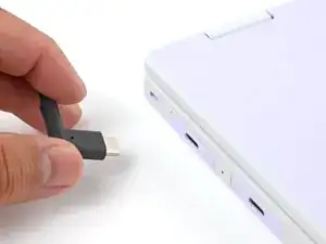
Before you begin repairs, unplug your laptop and shut it down from the operating system. This ensures that the laptop isn't in standby/suspend mode.
-
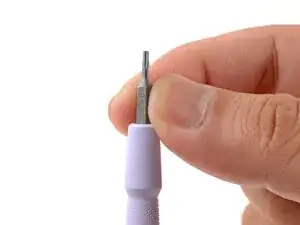
Make sure your Framework Screwdriver has the T5 Torx bit (labeled as T-5) facing outwards. If it's not, pull the bit out and flip it.
-
-
-
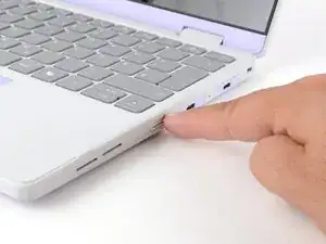
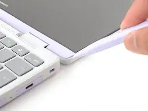
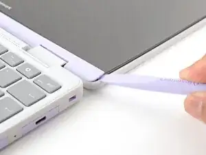
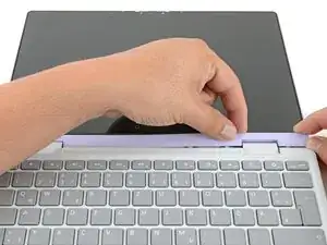
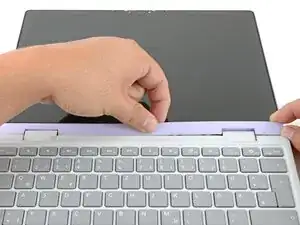
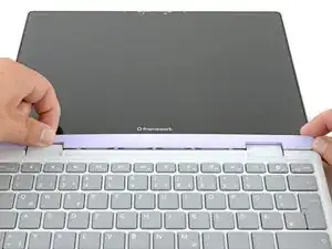
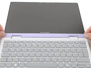
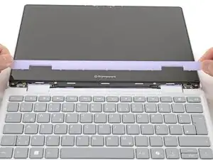
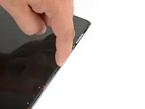
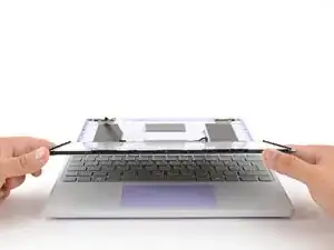
Use the flat end of your Framework Screwdriver to pry up the right edge of the Display Cover.
-
-
-
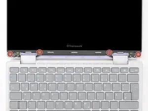
Use your Framework Screwdriver to remove the four 3.3 mm‑long T5 Torx screws securing the display to the Top Cover.
-
-
-
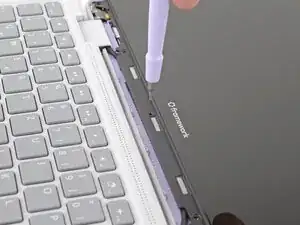
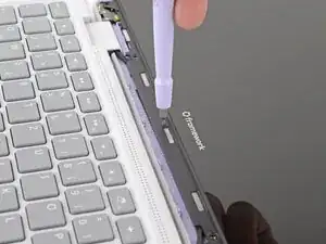
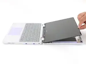
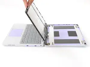
Insert the bit end of your Framework Screwdriver into the small hole on the display, below the Framework logo.
-
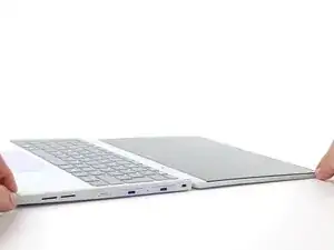
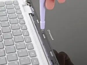
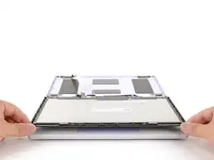
Slide the display down towards the hinge edge to release the tabs holding the top edge of the display in place.
-
-
-
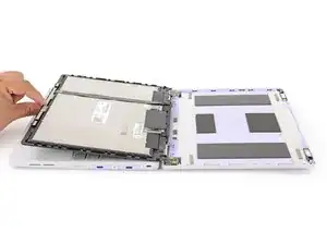
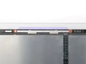
Use your Framework Screwdriver to remove the two 3.3 mm‑long T5 Torx screws securing the webcam bracket on the top edge behind the display.
-
-
-
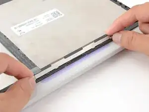
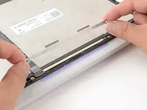
Use the flat end of your Framework Screwdriver to lift the webcam out of its recess.
-
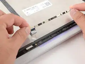
Flip the webcam over and gently hold it down with your fingers.
-
-
-
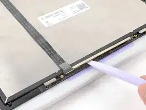
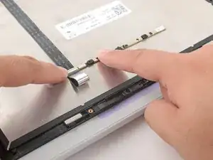
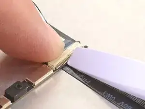
Use the flat end of your Framework Screwdriver or a fingernail to gently pry up the locking tab on the webcam cable ZIF connector.
-
-
-
Grab the webcam cable with your fingers and slowly peel it away from the display.
-
Carefully move the cable off of the display.
-
-
-
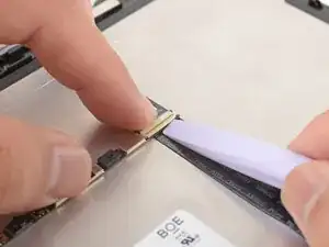
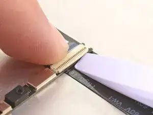
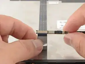
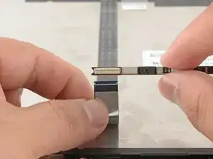
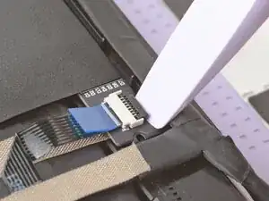
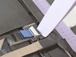
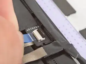
Use the flat end of your Framework Screwdriver or a fingernail to gently pry up the locking tab on the touch control ZIF connector near the hinge edge of the display.
-
Use your fingers to grab the touch control cable by the blue tab and slide the cable out of the connector.
-
-
-
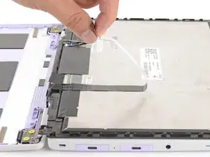
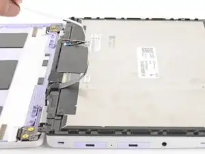
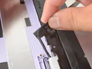
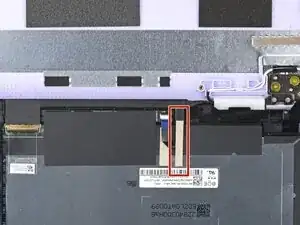
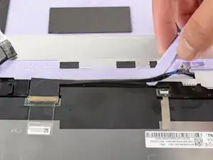
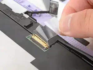
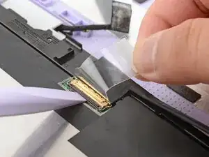
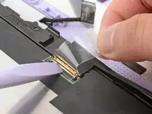
Slide the flat end of your Framework Screwdriver under the grounding tape securing the display cable.
-
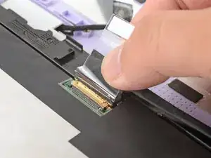
Lift slowly to separate the tape from the display.
-
-
-
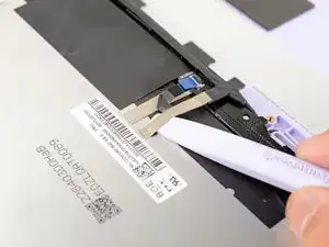
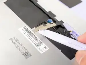
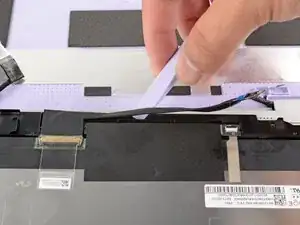
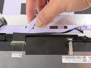
Slide the flat end of your Framework Screwdriver under the length of the display cable to separate it from the display.
-
-
-
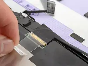
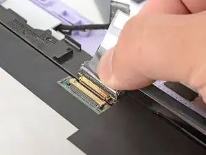
Use the flat end of your Framework Screwdriver to flip up the locking bar around the display connector.
-