Introduction
Follow this guide to remove and replace the antennas in your Framework Laptop 12.
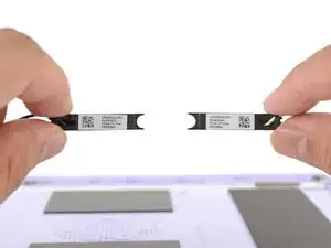
The Framework Laptop 12 has two antennas—one in each corner behind the top edge of the display. They connect to the wireless card via thin antenna cables, enabling both Wi-Fi and Bluetooth reception.
Removing the antennas is an extensive procedure. If you're having issues with Wi-Fi or Bluetooth reception, be sure to troubleshoot all other software and hardware possibilities before attempting this repair.
You'll encounter some component terms in this guide:
- The Input Cover is the part that contains the keyboard and trackpad.
- The Display Cover is the plastic bezel strip below the screen.
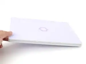
- The Top Cover is the plastic shell that houses the display.
- The Bottom Cover is the plastic shell that forms the bottom half of the laptop.
-
-
Before you begin repairs, unplug your laptop and shut it down from the operating system. This ensures that the laptop isn't in standby/suspend mode.
-
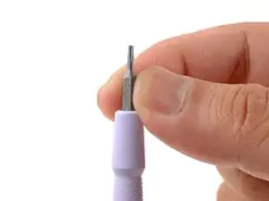
Make sure your Framework Screwdriver has the T5 Torx bit (labeled as T-5) facing outwards. If it's not, pull the bit out and flip it.
-
-
-
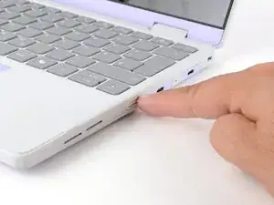
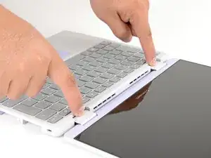
Use your fingers to flip the two Expansion Card latches (one for each side) into the unlocked position.
-
-
-
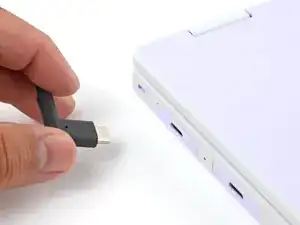
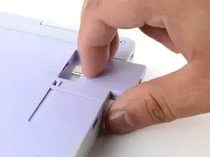
Grip the lip of an Expansion Card with your fingers.
-
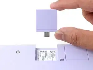
Pull the Expansion Card out of its slot and remove it.
-
Repeat this procedure to remove all remaining Expansion Cards.
-
-
-
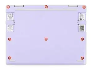
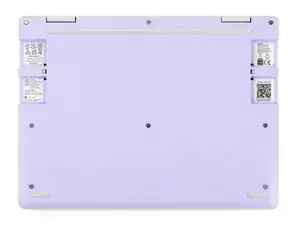
Use your Framework Screwdriver to fully loosen the eight captive T5 Torx screws on the bottom of your laptop.
-
-
-
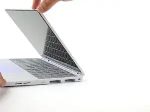
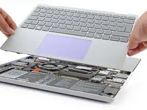
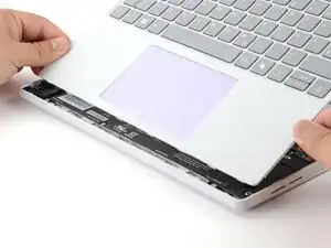
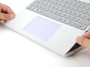
Use your fingers to grip the Input Cover in the hinge cutouts.
-
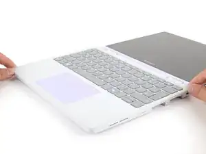
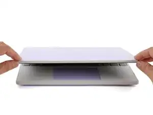
Lift upwards to swing the Input Cover up from the base of the laptop.
-
Remove the Input Cover.
-
-
-
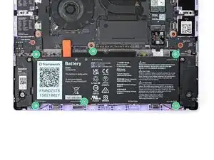
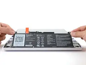
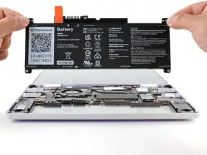
Use your Framework Screwdriver to loosen the six captive T5 Torx screws securing the battery.
-
-
-
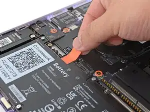
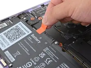
Grab the orange battery tab with your fingers and lift straight up to disconnect the battery.
-
-
-
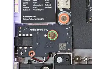
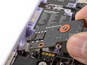
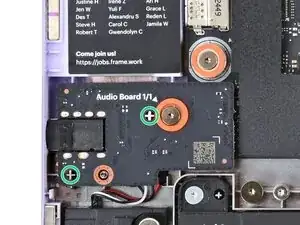
Use your Framework Screwdriver to loosen the captive T5 Torx screw securing the Audio Board along the left edge of the laptop.
-
-
-
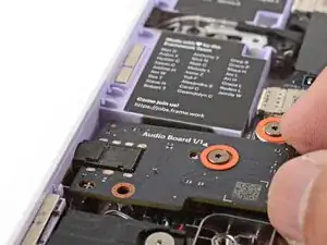
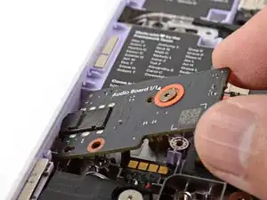
Use your fingers to lift the right edge of the Audio Board and pull it out of its recess.
-
Remove the Audio Board.
-
-
-
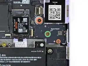
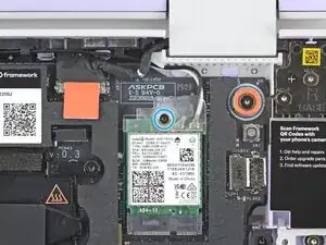
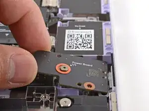
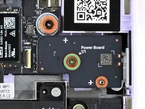
Use your Framework Screwdriver to loosen the captive T5 Torx screw securing the Power Button Board (labeled "Power Board").
-
-
-
Use your Framework Screwdriver to loosen the captive T5 Torx screw securing the Wi-Fi card bracket.
-
-
-
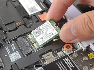
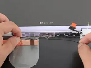
Grab the Wi-Fi card bracket with your fingers and slide it off the top of the Wi-Fi card.
-
Remove the bracket and store it in a safe location for reassembly.
-
-
-
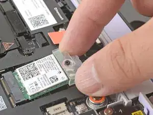
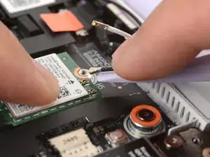
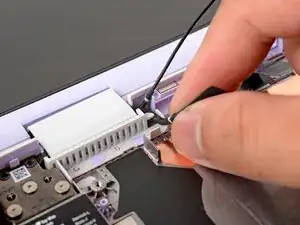
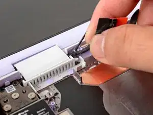
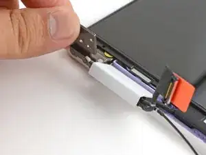
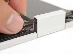
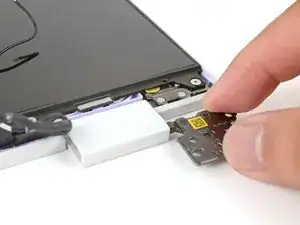
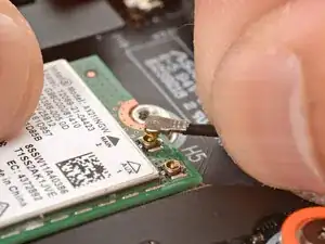
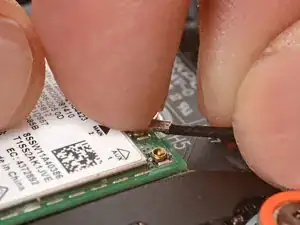
Press and hold the Wi-Fi card down with your finger.
-
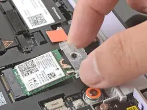
Slide the flat edge of your Framework Screwdriver under the white antenna cable, as close to the metal head as possible.
-
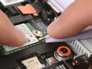
Gently lift the connector straight up to disconnect the white antenna cable.
-
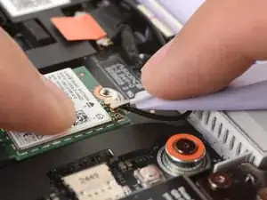
Repeat the procedure with the black antenna cable.
-
-
-
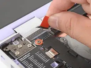
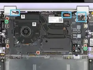
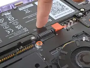
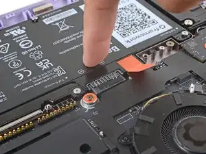
Use your fingers to grab the orange tab on the webcam cable, located near the left hinge.
-
Lift straight up to disconnect the cable.
-
-
-
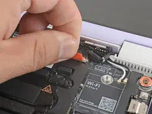
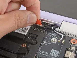
Use your fingers to grab the orange tab on the display cable, located near the right hinge.
-
Lift straight up to disconnect the cable.
-
-
-
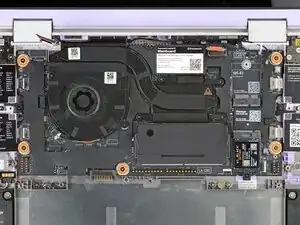
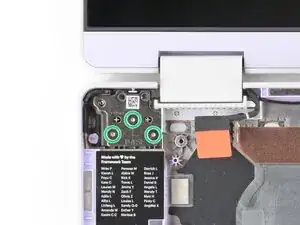
Use your Framework Screwdriver to loosen the five captive T5 Torx screws securing the Mainboard.
-
-
-
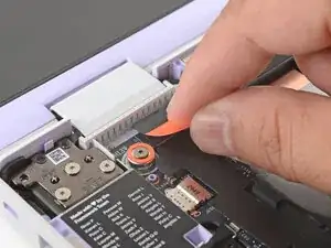
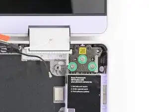
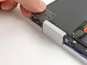
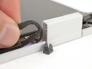
Use your fingers to lift the black plastic loop securing the antenna cable, near the heat vents by the left hinge.
-
-
-
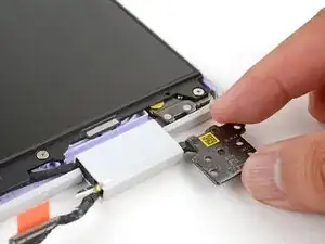
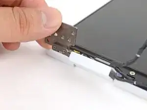
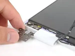
Use your Framework Screwdriver to remove the six (three per hinge) 4.5 mm‑long T5 Torx screws securing the two hinges.
-
-
-
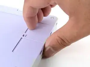
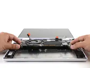
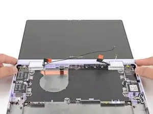
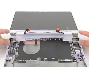
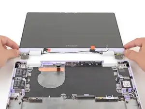
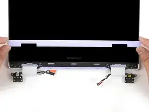
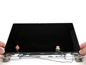
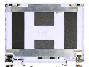
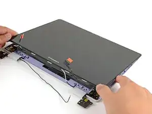
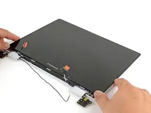
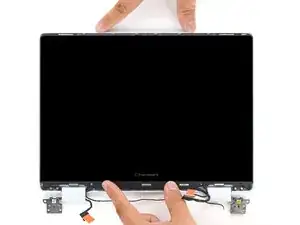
Use your fingers to lift the hinges over the Bottom Cover lip.
-
Separate the Top Cover from the Bottom Cover.
-
-
-
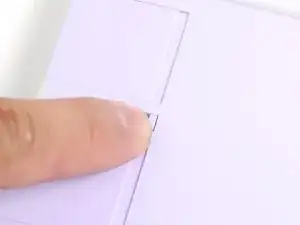
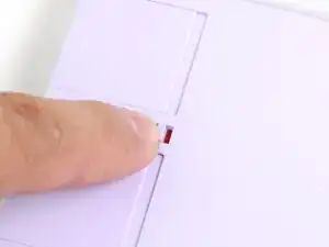
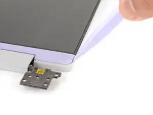
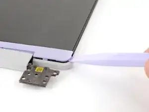
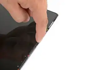
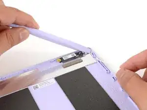
Use the flat end of your Framework Screwdriver to pry up the right edge of the Display Cover.
-
-
-
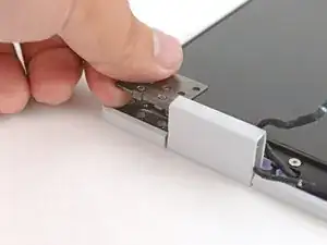
Use your fingers to grab the two cables coming out of the left hinge.
-
Pull gently to pop out the black cable clip and release the cables.
-
-
-
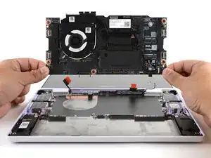
Use your fingers to twist both hinge plates back down so they lay flat on your work surface.
-
-
-
Use your Framework Screwdriver to remove the four 3.3 mm‑long T5 Torx screws securing the display to the Top Cover.
-
-
-
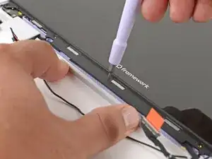
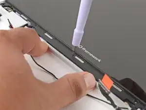
Use your fingers to hold the bottom edge of the Top Cover in place.
-
Insert the bit end of your Framework Screwdriver into the small hole on the display, below the Framework logo.
-
Slide the display down towards the hinge edge to release the tabs holding the top edge of the display in place.
-
-
-
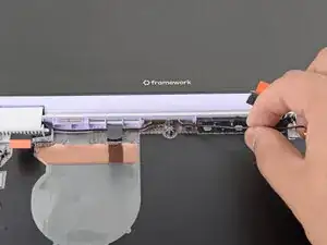
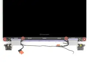
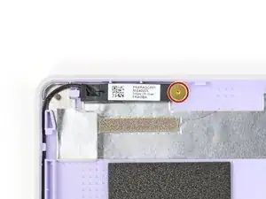
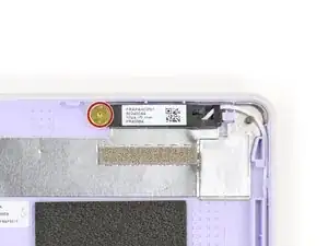
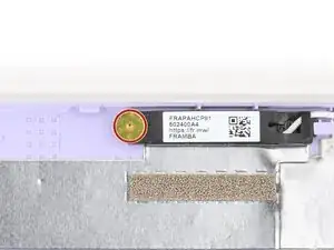
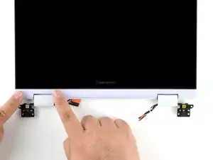
Use your Framework Screwdriver to remove the two (one per antenna) 2.5 mm‑long T5 Torx screws securing the antennas to the Top Cover.
-
-
-
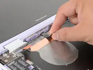
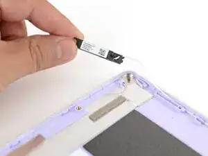
Use your fingers to lift the right antenna away from the Top Cover.
-
Carefully guide the white antenna cable out of its channel.
-
-
-
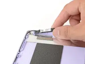
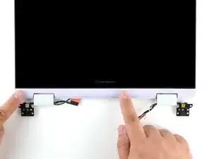
Use your fingers to lift the left antenna away from the Top Cover.
-
Carefully guide the black antenna cable out of its channel.
-
-
-
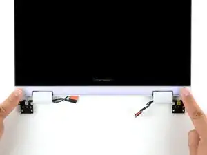
Use your Framework Screwdriver to install the two (one per antenna) 2.5 mm‑long T5 Torx screws to secure the antennas to the Top Cover.
-
-
-
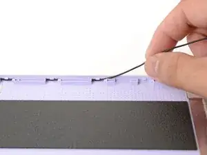
Use your fingers and your Framework Screwdriver to carefully guide each antenna cable back into its channel.
-
-
-
Lay the display in place in the Top Cover, such that the top edge of the display is slightly below the top edge of the Top Cover.
-
-
-
Use your fingers to slide the display upwards to latch the tabs on the top edge of the display.
-
-
-
Use your Framework Screwdriver to install the four 3.3 mm‑long T5 Torx screws to secure the display to the Top Cover.
-
-
-
Place the cable clip around the right hinge cables, where they were bent from being inserted into the hinge.
-
Use your fingers to press the clip into the hinge to secure the cables.
-
-
-
Make sure both cable clips are fully inserted into the hinges, so that they won't be snagged when the hinges pivot.
-
-
-
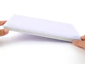
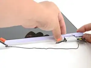
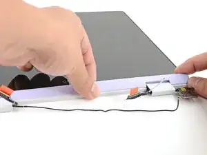
Lay the Display Cover in place below the display.
-
Use your finger to press along the length of the Display Cover to snap it onto the laptop.
-
-
-
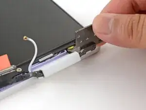
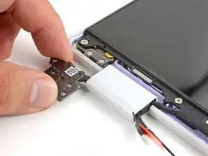
Use your fingers to lift the Top Cover hinges over the Bottom Cover lip.
-
Lay the hinges in place in the Bottom Cover.
-
-
-
Use your Framework Screwdriver to install the six 4.5 mm‑long T5 Torx screws securing the two hinges.
-
-
-
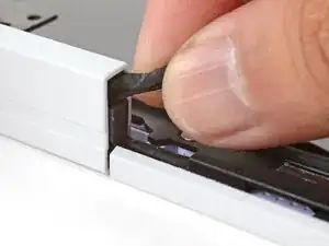
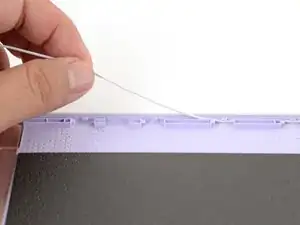
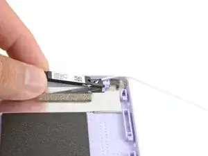
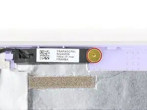
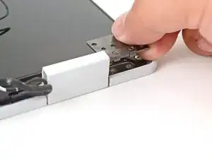
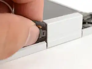
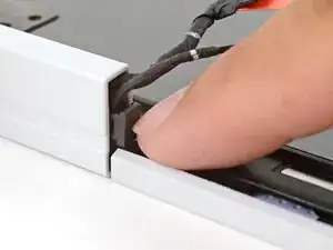
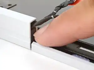
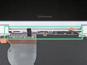
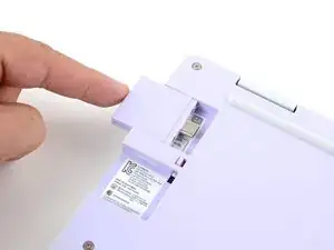
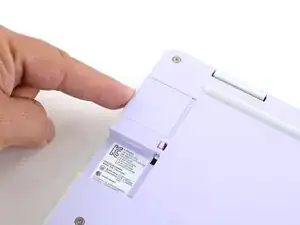
Use your fingers and your Framework Screwdriver to carefully press and guide the black antenna cable back into its channel.
-
Zoom in on the second image to see how the antenna cable sits in its channel.
-
-
-
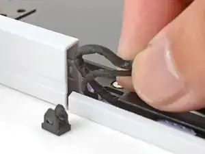
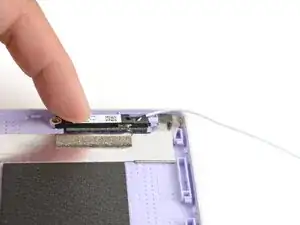
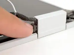
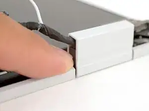
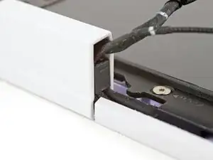
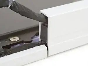
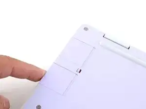
Press the black loop over the antenna cable and onto the Bottom Cover. If it doesn't stick, use a bit of thin double-sided tape to hold it down.
-
-
-
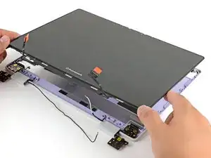
Carefully lay the Mainboard in the laptop.
-
Use the two alignment pins to help align the Mainboard to the laptop.
-
Be careful not to trap the webcam, display, and antenna cables under the Mainboard as you set it in place.
-
-
-
Use your Framework Screwdriver to tighten the five captive T5 Torx screws to secure the Mainboard.
-
-
-
Use your fingers to grab the orange tab on the display cable, located near the right hinge.
-
Align and press the display cable straight down onto its connector.
-
-
-
Use your fingers to grab the orange tab on the webcam cable, located near the left hinge.
-
Align and press the webcam cable straight down onto its connector.
-
-
-
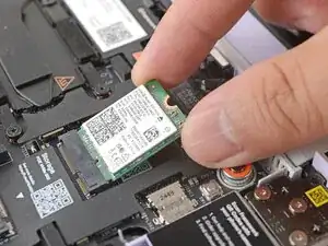
Align the Wi-Fi card's gold contacts and notch with the socket on the Mainboard.
-
Insert the Wi-Fi card into the socket at a shallow angle. The gold contacts should mostly be covered by the socket.
-
-
-
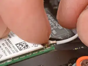
Hold the Wi-Fi card down with your finger.
-
Position the black antenna cable connector over the left Wi-Fi card's coaxial socket.
-
Use your finger to press the connector into place. You should feel a faint click, and the cable will stay attached to the socket by itself.
-
Repeat the procedure with the white antenna cable.
-
-
-
Use your Framework Screwdriver to tighten the captive T5 Torx screw to secure the Wi-Fi card.
-
-
-
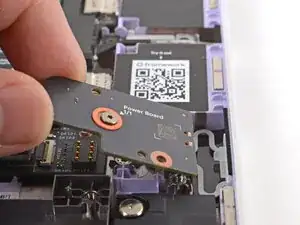
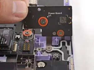
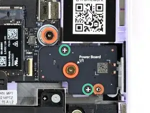
Use your fingers to lay the Power Button Board in place.
-
Use the two plastic pins on the laptop to align the Power Button Board.
-
-
-
Use your Framework Screwdriver to tighten the captive T5 Torx screw to secure the Power Button Board.
-
-
-
Insert the Audio Board into the laptop at an angle to help align the headphone jack.
-
Use the two plastic alignment pins on the laptop to help with final alignment.
-
-
-
Use your Framework Screwdriver to tighten the captive T5 Torx screw to secure the Audio Board.
-
-
-
Use your Framework Screwdriver to tighten the six captive T5 Torx screws to secure the battery.
-
-
-
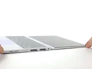
Angle the bottom edge of the Input Cover towards the base of the laptop.
-
Align and insert the bottom edge of the Input Cover into the base of the laptop.
-
Lower the Input Cover's top edge onto the laptop until the magnets snap it in place.
-
-
-
Use your Framework Screwdriver to tighten the eight captive T5 Torx screws on the bottom of your laptop.
-


You finished fixing your Framework Laptop!
Take your e-waste to an R2 or e-Stewards certified recycler.
If you need help, contact Framework support.