Introduction

If you have a Dell Inspiron 13-7347 laptop (Computer model Inspiron 7347) and the screen is cracked, chipped, unresponsive, or maybe your screen is flickering, you may use this guide for removal and replacement of the Display Assembly.

A "display assembly" is the complete module used to show images or information on a device, such as a phone, computer, or TV. It typically includes the display panel (like an LCD or OLED), its supporting circuitry, and sometimes a bezel or housing. You may want to replace the display assembly if it has cracks or chips, the screen is unresponsive, ghost touching, or it has display issues such as flickering, has distorted colors or even dead pixels. Below is a step by step process on how to replace the display assembly.

  1. GpqFNtPQa5WEBIOY
    GpqFNtPQa5WEBIOY
    CCBPuJm6c46rgcq6
    nYHnv5ynThWHXnS2
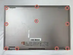
    • Flip the device over, so that the back is facing up.

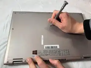
    • Using a Phillips screwdriver, remove the 10 2.5mm x 8mm screws

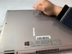
    • Use the suction cup to lift off the back case.

  2. BwyOVvRIGTaPQXLG
    BwyOVvRIGTaPQXLG
    tXN6ktsSyGHYrMWH
    3PnCjNOlfHGGXMwg
    • Remove the two 2mm x 3mm screws that secure the battery to the device.

  3. FkDawYuKPvamgRZ1
    FkDawYuKPvamgRZ1
    wUR14jEuHwh4DDkR
    CUKBZsiIkWRiZYbt
    • Unplug the cable that connects the USB / SD Reader IO Board to the motherboard.

  4. Gl1jSePK2PLZQddg
    Gl1jSePK2PLZQddg
    aMlMYGoOMZp4ngCT
    AwcWGrC1qqQnmEtV
    • Lift the battery steadily from the device.

    • Tilt the battery upward while removing.

  5. VcEDLiF2KmSvwcC1
    VcEDLiF2KmSvwcC1
    LGZifh5K1QHIKVQG
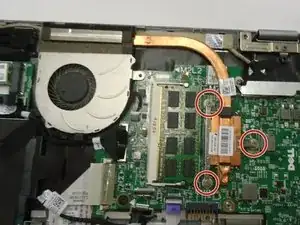
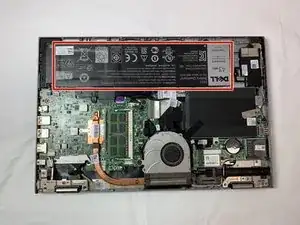
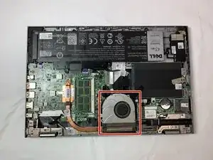
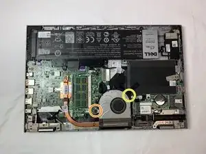
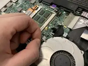
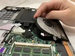
    • You should be able to identify the fan.

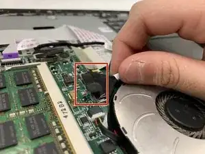
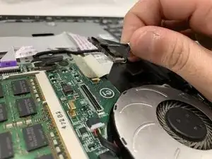
    • This is the 2mm x 2mm JIS #00 screw.

    • This is the 2mm x 3mm JIS #00 screw.

  6. LhCSpiVK16WfENdv
    LhCSpiVK16WfENdv
    S41jof2KysR5HkxT
    • Remove the 2mm x 2mm JIS #00 screw.

    • Remove the 2mm x 3mm JIS #00 screw.

  7. qT6b1KSxPuSXjqN5
    qT6b1KSxPuSXjqN5
    oLuockmSXnm6JZLx
    • Detach the cable that connects the fan and the motherboard.

    • The cable is extremely fragile.

  8. y4WMFYIVqDQP3t1V
    y4WMFYIVqDQP3t1V
    fmPGIbPd6OnEyXKt
    • Detach the cord that connects the fan and the motherboard.

    Do not need this step in order to disconnect the fan.

    Kayji Arai -

  9. GnIBTaYAxpTcoZWC
    • Remove the fan.

  10. 1rrgVuEGZIFvsPqU
    1rrgVuEGZIFvsPqU
    CjRqbWUXWn2Juw1K
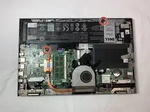
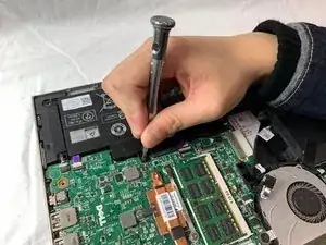
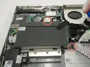
    • Using a Phillips #0 screwdriver, loosen and remove the two 3.0 mm hard drive screws.

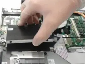
    • Lift the hard drive up and out of the device.

  11. 4RTYUtFMDGta6prn
    4RTYUtFMDGta6prn
    KDDYDnAApFNZQNsl
    NOjiqLJUa3C2rSGO
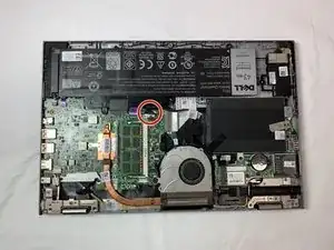
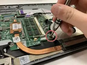
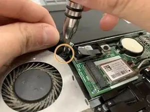
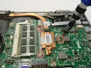
    • Using a Phillips #0 screwdriver, loosen the three 3.0 mm heat sink screws.

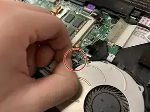
    • Remove the Heat Sink.

    • When reinstalling the heat sink, be sure to clean both contact surfaces with isopropyl alcohol and reapply thermal paste.

  12. LX2iEBKh4rY4RKJx
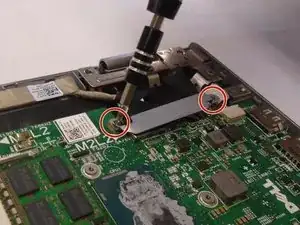
    • Using a Phillips #0 screwdriver, remove the two 5.0 mm screws on the metal bracket.

    • Remove the metal bracket.

  13. RaPWCyvwwrc5wR3Y
    • Loosen and reposition the display cable.

    • The display cable will not be removed. Do not attempt to remove the display cable.

  14. mW22PJPWI1IEpvqO
    mW22PJPWI1IEpvqO
    ReK1durlrUlUpMul
    XYyYltIWraorE1FT
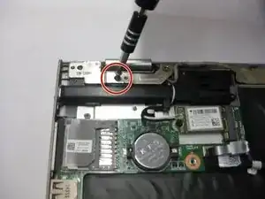
    • Using a Phillips #0 screwdriver, remove the 5.0mm screw on the left display hinge bracket.

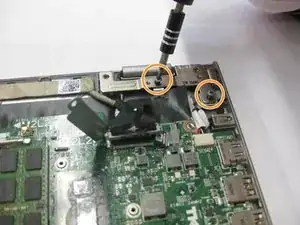
    • Using a Phillips #0 screwdriver, remove the two 5.0mm screws on the right display hinge bracket.

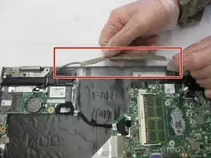
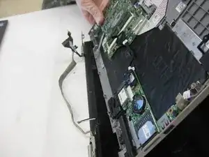
    • Lift and remove the display assembly.

Conclusion

To reassemble your device, follow these instructions in reverse order.

Kyle Smith

Member since: 02/10/19

331 Reputation

0 comments