Introduction
In this guide, we will show you how to remove and replace the Camera.
-
-
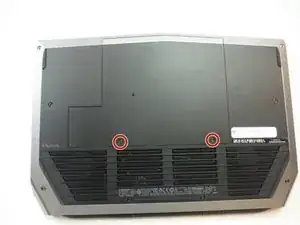
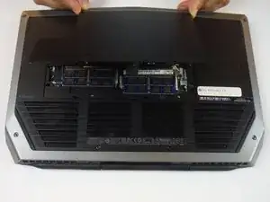
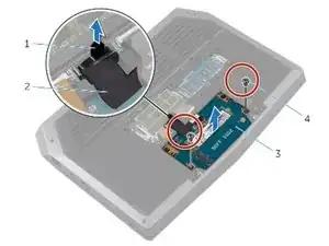
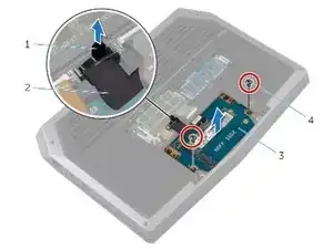
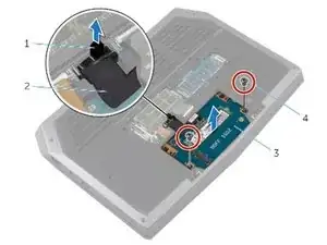
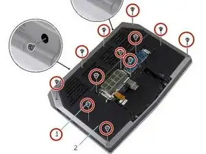
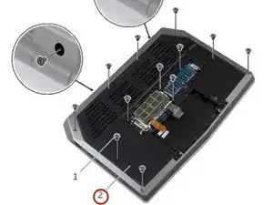
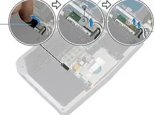
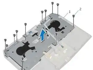
Remove (2) 5 mm Phillips head screws attaching the small access panel to the base using a Phillips # 1 screwdriver.
-
-
-
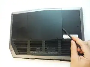
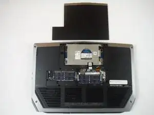
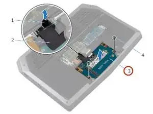
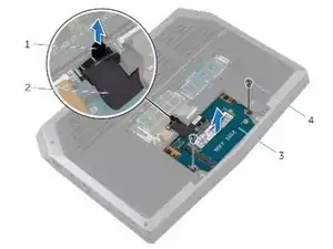
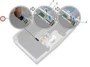
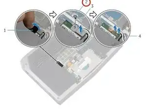
Using the pull tab, pivot the solid-state drive bracket and peel off the bracket from the tabs on the computer base.
-
-
-
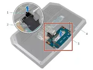
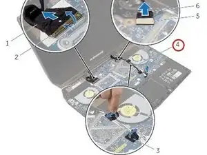
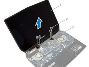
Lift the solid-state drive assembly off the computer base.
-
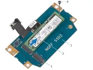
Make sure the screws are off the solid-state assembly.
-
-
-
Replace the screw that secures the solid-state drive assembly with the screw holes on the computer base.
-
-
-
Align the screw holes on the solid-state drive assembly with the screw holes on the computer base.
-
-
-
Align the screws on the solid-state drive bracket with the screw holes on the solid-state drive assembly.
-
-
-
Replace the screws that secure the solid-state drive bracket to the solid-state drive assembly.
-
-
-
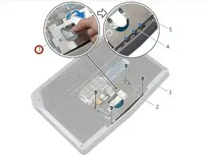
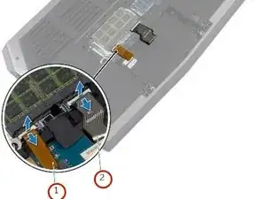
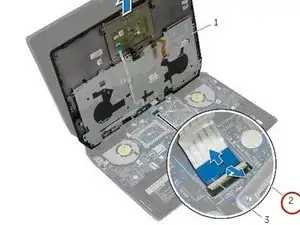
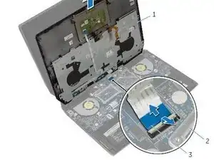
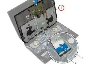
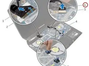
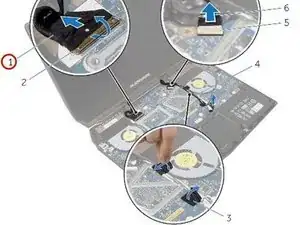
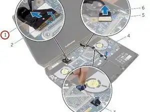
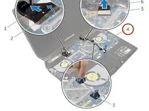
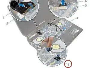
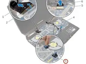
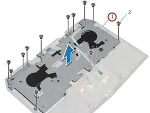
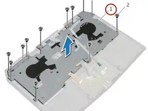
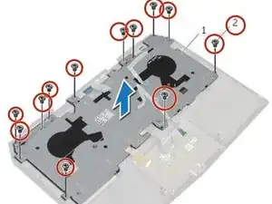
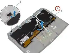
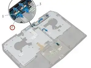
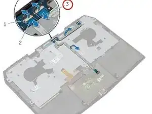
Lift the latches and disconnect the keyboard and keyboard-backlight cables from the system board
-
-
-
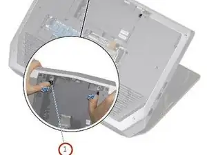
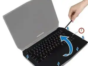
Lift the computer base slightly and push the release tabs on the palm-rest assembly until it pops out.
-
-
-
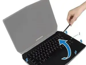
Remove the Keyboard.
-
Remove the power-button board.
-
Remove the status-light board.
-
Remove the touchpad.
-
-
-
Replace the touchpad.
-
Replace the status-light board.
-
Replace the power-button board.
-
Replace the keyboard.
-
-
-
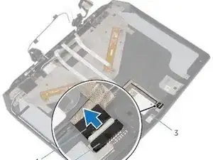
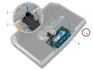
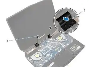
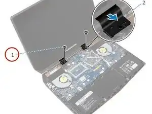
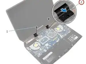
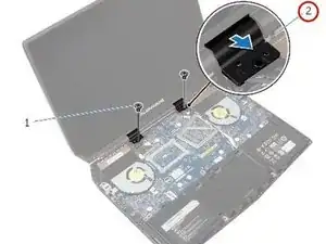
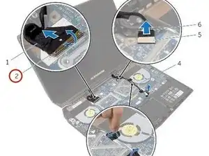
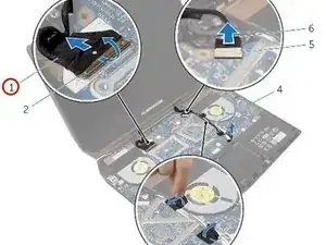
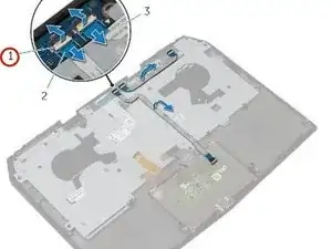
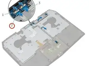
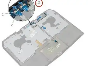
Disconnect the logo-board cable from the system board and remove it from the routing guides on the display hinges.
-
-
-
Route the logo-board cable through the routing guides on the display hinge and connect the logo-board cable to the system board.
-
-
-
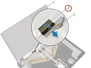
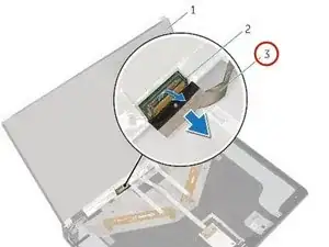
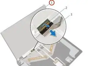
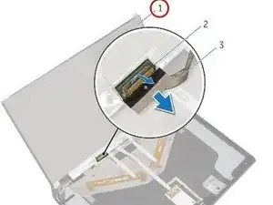
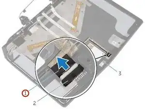
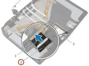
Slide the display cable into the connector on the system board and press down the latch to secure the cable.
-
-
-
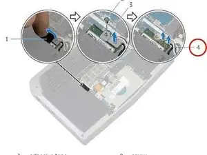
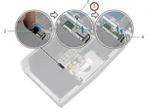
Lift the connector latches and disconnect the touchpad cable and the status-light cable from the power-button board.
-
-
-
Align the screw holes on the keyboard bracket with the screw holes on the palm-rest assembly.
-
-
-
Slide the touchpad cable and the status-light cable into their respective connectors on the power-button board and press down the latches to secure the cables.
-
-
-
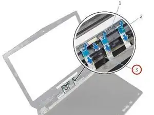
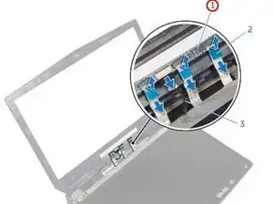
Slide the display-board cables to their respective connectors on the logo board and press down the latches to secure the cables.
-
-
-
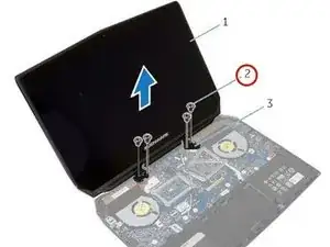
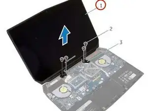
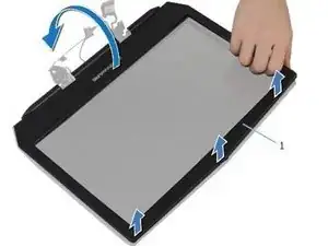
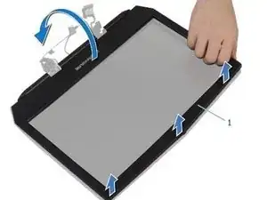
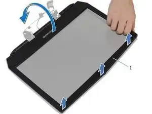
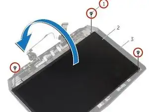
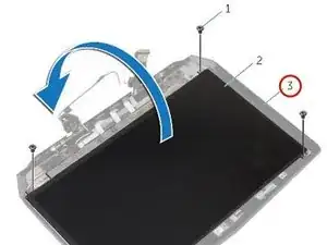
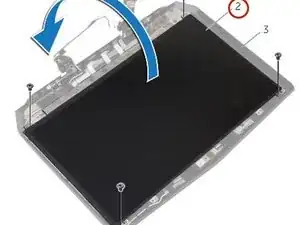
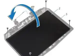
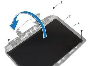
Align the display bezel with the display back-cover and gently snap the display bezel into place.
-
-
-
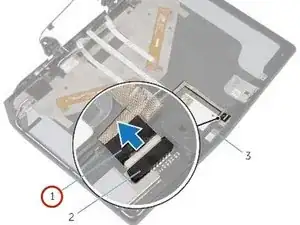
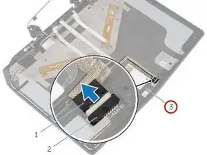
Connect the display cable to the NEW display panel and press down on the connector latch to secure the cable.
-
-
-
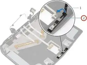
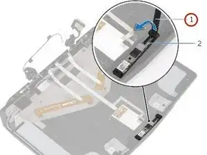
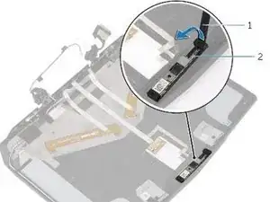
Using the alignment posts place the NEW camera module on the display back-cover and snap it into place.
-


To reassemble your device, follow these instructions in reverse order.