0

I want to undervolt protect a series of 3 Li-ion cells. The load is a voltage booster with initial 5 amp usage for 5 seconds. Then power consumption is reduced to 5 watts. (It works ok on battery.) (A BMS circuit is not suitable for me.)

I want to cut off the power at 10.5 volts. My priorities are: low voltage drop, low power consumption by protection circuit.

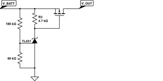
I found these two circuits. Also is driving a relay instead of direct connection better?:

found this transistor based and this:

And this Tl431+transistor based circuit

brhans
  • 14,723
  • 3
  • 35
  • 51
jzeds1491
  • 11
  • 3
  • 1
    ErikRs answer looks good A suitably low Rdson MOSFET is a much better solution than a bipolar transistor solution. | The MOSFET transistor linked solution is very poor. The one you showed the cct of is better. – Russell McMahon Jul 12 '21 at 03:39
  • 2
    When you are building an undervoltage lockout circuit, you need to give it some hysteresis. When the undervoltage protection kicks in, the battery gets disconnected and stops supplying power to the boost converter. This causes the battery voltage to rise slightly and the undervoltage circuit will no longer detect an udervoltage and it reconnects the battery again which causes its voltage to drop and the circuit to cutoff power. The circuit will cycle like this. Adding some hysteresis will prevent this. – Prathik Prashanth Jul 12 '21 at 04:34
  • @Prathik Prashanth ,thanks,that hysteresis you mentioned is likely to be very important.cause az you said my empty batteries raised voltage when in idle for some minutes. whats is a hystersis circuit? – jzeds1491 Jul 20 '21 at 06:46

2 Answers2

2

For using the TL431 as a comparator I'd recommend reading this TI publication:

Using the TL431 for Undervoltage and Overvoltage Detection - SLVA987A https://www.ti.com/lit/an/slva987a/slva987a.pdf?ts=1626026654019

In the TL431 circuit here is where your current is being consumed:

  • around 2.5mA in the voltage divider
  • between 100 and 200mA of base current to drive the PNP at 5A

In fact, you're exceeding the I_KA limit of the TL431 which has a max I_KA current of 100mA.

V_CE(sat) for the PNP is around 1.5V so that will be taken off of your battery voltage.

To improve things you can stiffen up the resistive divider. The TL431 requires an Iref of about 4uA. Budgeting 50uA for the divider means the divider could have a total resistance of around 200 Kohms.

Switching to a P-MOSFET would eliminate the need for the base current.

Note that the TL431 needs 1mA in order to regulate. So I'd try something like this:

schematic

simulate this circuit – Schematic created using CircuitLab

ErikR
  • 4,987
  • 12
  • 18
  • This seems pretty good for a TL431 circuit. One could argue that 50 uA is kind of a lot for an over-discharged battery. I am sure it is possible to get much lower one way or another. Maybe with a voltage monitor IC. Or using a micropower comparator and reference. – user57037 Jul 12 '21 at 03:56
  • Using a TL431 you need to spend 1mA just for I_KA. Not such a big concern for this application, but it could be for other battery powered projects. Another option if you're really concerned about power usage you could use TI's "Advanced" TL431 -- the ATL431 -- which has a I_KA(min) of 35uA and a quiescent I_ref of 100 nA. – ErikR Jul 12 '21 at 04:35
  • thanks for this simple yet clever design , i never worked with mosfets ,which model/ type is prefered here? ( – jzeds1491 Jul 12 '21 at 10:58
  • @mkeith & ErikR , one question : For a 5 to 15 watt load on 3cell (liion), is using a relay recommended here? or mosfet will handle is with ease? – jzeds1491 Jul 12 '21 at 11:11
  • A relay would require more current to keep the coil energized. A P-MOSFET will incur less than 100 millohms in resistance. Almost any P-MOSFET in a TO-220 package will work - e.g. IRF4905, IRF9640, FQP27P06, NDP6020P, ... – ErikR Jul 12 '21 at 16:35
  • I think MOSFET. I would not be looking at relays for this application. – user57037 Jul 12 '21 at 16:38
0

Simple with 10v zener diode and P-mos, self-consumption almost negligible. Blue is battery voltage, green is 2 ohm load current.

enter image description here

enter image description here

  • great! ill check it right away ,seems perfect..any eqvalant to irf7404? – jzeds1491 Jul 12 '21 at 11:02
  • For a 5 to 15 watt load on 3cell (liion), is using a relay recommended here? or mosfet will handle is with ease? – jzeds1491 Jul 12 '21 at 11:08
  • The relay would drain your batteries at least few mA. However, its also possible. Mosfets drain almost nothing. You can pick whatever P-chan mosfet available in store with raiting 20v Vds more, Id 10A at least, small Rds_on if prefferable. –  Jul 12 '21 at 14:04
  • Thanks, I never knew MOSFETs are that efficient, it'll be very helpful from here on. – jzeds1491 Jul 12 '21 at 15:45