I'm playing around with an old MagSafe charger and designing a circuit to be powered off it.
From what I've read, the charger's safety mechanism first provides 6V with a current limit of around 100uA. The load is expected to apply a resistive load that pulls that voltage down to around 1.7V for a second or so. This seems to be some sort of protection against shorts (i.e. a short would have pulled the voltage close to 0V). Only after one second and the charger is happy there is no fault does it then send the full 14-20V down. It makes sense to do this since the 85W of power the charger is able to deliver is something that can seriously ruin your day if shorted.
Unfortunately, that means extra complications if I'm designing a circuit to be powered entirely off the charger. In particular, I don't want to provide power to the rest of my circuit until the charger is delivering full power.
I came up with a scheme to achieve this by taking advantage of a N-channel MOSFET with a high threshold voltage to do this.
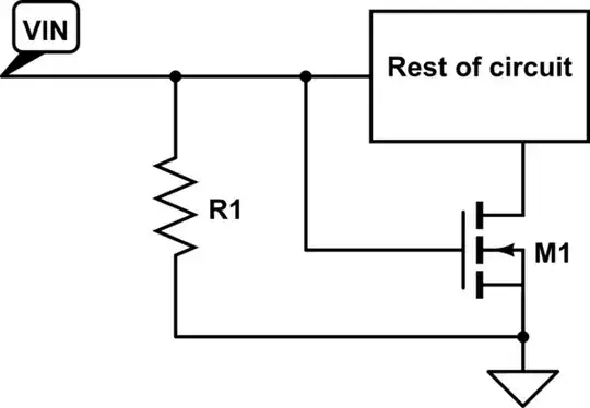
simulate this circuit – Schematic created using CircuitLab
When VIN is at 6V, M1 will not turn on and R1 will be the only load being driven (which will pull down the voltage as per the spec). When the charger starts delivering the full voltage (around 14-20V), VIN will be above the threshold voltage of M1 which will deliver power to the rest of the circuit.
Now, in practice, I understand that a MOSFET is not really completely off if a lower-than-threshold-voltage is applied to the gate. Normally this isn't a problem but in this case, I can't really leak more than 100uA into the rest of the circuit lest the safety circuit thinks there's a short circuit.
Will this actually be an issue? What parameter should I look for when shopping for MOSFETs? Is the idea sound or have I missed something blatantly obvious?