It would be very nice to be able to insert a little "phase shift" circuit into a data line of mine to shift it by one clock - about 200ns - instead of doing it in software which will be difficult and break compatibility with other hardware which runs the same software. The timing will always be fixed. I was thinking of a series C with parallel R but wasn't sure how if it would phase shift; also, it would remove the DC component which might cause issues with the following logic. The solution needs to be as small and as cheap as possible, ideally involving no "phase shift IC", if such a thing exists.
Asked
Active
Viewed 636 times
1
-
659.95849m of wire? – Majenko Jun 22 '11 at 17:19
-
Use an RC circuit followed by a Schmitt trigger buffer? D flip flop? – endolith Jun 22 '11 at 17:28
-
1@Matt - speed in a copper conductor is typically only 2/3 the speed of light in vacuum. – stevenvh Jun 22 '11 at 17:29
-
1@stevenvh good point, so cut a bit of wire off then. 20m less should do the trick... – Majenko Jun 22 '11 at 17:34
-
4@Matt Jenkins: are you a mathematician, or what? Engineers never use more than 3 significant digits! (In some situations pi = 3) – Federico Russo Jun 22 '11 at 17:36
-
@Matt - you can't seriously mean 20.00000m!? – stevenvh Jun 22 '11 at 17:39
-
I think he means 59.95849m of wire minus 20m or so. It's kindof like saying Pi is 3.15743268643 +-1%, which is technically correct. – Olin Lathrop Jun 22 '11 at 17:46
-
you said 'data line' - is this a digital signal or an analog one? b/c if it's digital, a D-FF and a 5MHz clock, problem solved? if it's analog though.. dunno. – JustJeff Jun 23 '11 at 01:07
-
@self - Apparently the IoR (index of refraction) of copper is 1.1, not 1.5. But I do remember being taught that a signal in a PCB trace will travel 20cm/ns. How's that? – stevenvh Jun 23 '11 at 06:37
-
@JustJeff, endolith - the FF was also my idea for a second (it's obvious, isn't it?), but it quickly dawned to me that you're syncing the data to the clock, while they may be totally unrelated. – stevenvh Jun 23 '11 at 07:30
-
@stevenvh - if it's an asynchronous digital signal that's going to be read by a processor, it's going to be sync'd to a clock eventually anyway, so sometimes this is not such a problem. otoh, there are many other possibilities (left open by the question) in which it would, as you say. – JustJeff Jun 23 '11 at 10:20
5 Answers
5
This sounds like another case of a pre-supposed solution. Explain the problem you are trying to solve one or two levels up. Wanting a delay line is a red flag kludge alert. That doesn't mean there are never good reasons for delays, but that usually when I've seen delays proposed they were results of less than ideal higher level design.
What you apparently want is a delay. This is not the same as a phase shift except at a single frequency. For example, 200ns is a 90 degree phase shift at 1.25MHz. That same 90 degree phase shift at 5MHz is 50ns.
However to answer your question in case there really is a legitimate reason for a delay, you can do this cheaply and simply with a low pass filter between two logic gates. R and C in parallel in the signal path is a high pass filter, not a low pass, although they would not remove the DC component. You want the resistor in series with a digital output followed by a capacitor to ground.
The switching thresholds of digital gates are not well guaranteed. You seem to want something cheap and simple, so maybe that's good enough. The switching thresholds of CMOS gates are usually about half the supply voltage, so you want the R-C filter to decay 1/2 the way to its final value in 200ns. The log(2) = .693, so you want .693 time constants to be 200ns. Therefore
R * C * 0.693= 200ns
R * C = 286ns
R = 286ns / C
C = 286ns / R
One example combination is 2.9 KOhms and 100pF.
If you need more accuracy, then the second gate should be a comparator instead of just a ordinary logic gate. That way the switching threshold is well known and controlled.
Olin Lathrop
- 313,258
- 36
- 434
- 925
-
1It just occurred to me (I added it to my answer as well) that this causes jitter which could be a problem. The high/low voltage won't have completely restored if edges follow each other closely, and thus the time to the gate's treshold will vary. – stevenvh Jun 23 '11 at 00:01
-
-
@stevenh: Yes, the delay will be less if it was recently preceeded by another edge. In other words, the system needs a little time to reset between edges. The OP was very vague what he wanted, so we don't know if the simple R-C delay method is appropriate. I still think this smells like getting painted into a corner by bad design one or two levels up. – Olin Lathrop Jun 23 '11 at 11:54
-
you're probably right, and in a professional setting you want an efficient, reliable and cheap solution to whatever the actual problem was. But when the clock isn't ticking I find it interesting to look into this kind of problems. – stevenvh Jun 23 '11 at 12:24
2
Well, there are delay ICs, I remember them for delays in the < 1ns order. edit The Micrel SY89297U has a programmable delay up to 7ns, so you would need 29 of them, but you can fine-tune with 5ps resolution! :-)
The thing with RC is that you won't get the same delay over the full spectrum of your edges, so they will be distorted. You can restore the edge by following the RC with a gate. However, it occurred to me that this will cause jitter if the edges aren't evenly spaced. If an edge is closely followed by another one, the voltage over the cap won't have reached the V+ (GND) yet, and the gate's threshold will be reached sooner. This jitter may considerably reduced if the single RC + gate is replaced by a series of them, with short time constants.
Can't you use a few older CMOS gates (CD4000), they have a typical delay of 60ns, so 3 gates will come close. You can add a pair of low-power Schottky gates to get a better match.
No wait, I've got it! :-) SDL (for Surface Acoustic Wave Delay Line). I've never worked with SAW (Surface Acoustic Wave) devices before, in fact I've never even seen one, but there may be devices which have a delay around 200ns, or SAW filters with a tap at that time.
edit
This one will only work if successive edges in your signal are more than 200ns apart. The idea is to use MMVs to create a new edge 200ns after each existing one, and use an SR-flipflop to reconstruct the signal. You feed the signal to two MMVs (T=200ns), the first one directly, the second one inverted. The first one will time out (falling edge) 200ns after a rising edge of the input signal, the second one will time out 200ns after a falling edge of the signal. From those falling edges create short pulses
and feed them to the set and reset input of the SR-flipflop, resp.
You'll have to trim one of the MMVs so that a 50% duty cycle input signal also gives 50% duty cycle at the output.
stevenvh
- 145,832
- 21
- 457
- 668
-
a SAW device could work, but they're relatively narrow band, so you'd have to modulate everything onto a carrier, and then demod it to get it back. – JustJeff Jun 23 '11 at 01:09
-
-
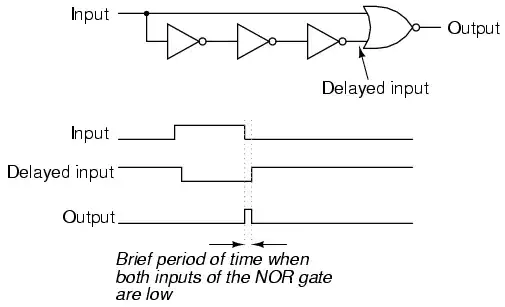
I've seen the edge detector from the image before, but it caught both edges? – Federico Russo Jun 23 '11 at 06:44
-
JustJeff: SAWs look interesting, but when I Googled them I couldn't find any actual products. Any links? Thanks – Federico Russo Jun 23 '11 at 06:46
-
1@Federico - There are a few variants to the circuit. If you replace the NOR with an EXNOR you get both edges. If you use an AND you get only the rising edges. – stevenvh Jun 23 '11 at 07:05
1
Maxim do a part from their Dallas range, the DS1100 series. If you can find a local supplier, the DS1100-250 using tap 4 would give 200ns, or the DS1100-500 at tap 2. Whether this is cheap enough for you (around 2.80 GBP at 50 off from RS) I don't know, but it is a single chip solution.
-
So I try to find an original solution and there comes this guy Martin spoil everything! =) – stevenvh Jun 23 '11 at 08:22
-
@stevenh - hey don't complain, your solution has more votes than mine, and meets Thomas's requirement that it isn't a "phase shift IC". But I think he was hoping for an R/C/Transistor solution. – Martin Jun 23 '11 at 10:36
0
If the data out is synchronous, then we can expect to see something like this:
               ___________________             __________
    DIN ______|________|          |___________|          |______

             _____       _____       _____       _____       ___
    CLK ____|     |_____|     |_____|     |_____|     |_____|

         ____              ___________             __________
    DOUT ____|____________|           |___________|          |___
and delaying DOUT by one clock period can easily be accomplished like this:
             ______
    DOUT>---|D    Q|---DDLY
            |      |
    CLK>----|>     |
            |______|
yielding:
               ___________________             __________
    DIN ______|________|          |___________|          |______

             _____       _____       _____       _____       ___
    CLK ____|     |_____|     |_____|     |_____|     |_____|

         ____              ___________             __________
    DOUT ____|____________|     1     |___________|          |___

         _________________             ____________           ___
    DDLY _________________|___________|      1     |_________|
EM Fields
- 17,527
- 2
- 19
- 23
-
Oops... Didn't notice this (the dflop solution) had already been posted. – EM Fields Jun 08 '14 at 09:05
0
If you want to delay something by one clock, use a D-type flip flop. Simple, cheap, and no concerns about calibration.
Chris Stratton
- 33,491
- 3
- 44
- 90
-
Like we said in comments to the question, this will sync the signal to FF's clock, while it may be asynchronous. @Thomas isn't completely clear about this. – stevenvh Jun 23 '11 at 16:45
-
@stevenh He specifically says he wants to shift it by one clock and mentions doing it in software as an undesired alternative, which strongly suggests to me that treating it as synchronous will work. – Chris Stratton Jun 23 '11 at 16:51
-
that's one way to read it. You could also say that he wants to delay the signal by 1 period of the controller's clock, but that the signal holds no relation to that. Only @Thomas knows. – stevenvh Jun 23 '11 at 16:58